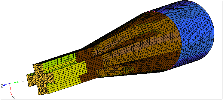
Tool deflection analysis is performed to study how the tool deforms because of the forces arising out the polymer. This is also used to simulate how a metal insert, such as the wire in wire coating die, can move under these forces and reduce the product quality.
The model files for this tutorial are located in the file mfs-1.zip in the subdirectory \hx\MetalExtrusion\HX_1301. See Accessing Model Files.
To work on this tutorial, it is recommended that you copy this folder to your local hard drive where you store your HyperXtrude data, for example, "C:\Users\HyperXtrude\” on a Windows machine. This will enable you to edit and modify these files without affecting the original data. In addition, it is best to keep the data on a local disk attached to the machine to improve the I/O performance of the software.
| 1. | Load the model HX_1301.hm. The model is already meshed and BCs are created for polymer components. This model was meshed using the Plate Meshing Wizard and then manually modified to combine the land and manifold1 interface boundaries with the tool. The current version of the wizard cannot handle a model with tool, hence the subsequent steps in the tutorial are done outside the wizard. |
|
| 1. | Click on the Model browser tab to display it. Right click on Component and select Create. |
| 2. | Enter the component name as Plate3D and click Create. |
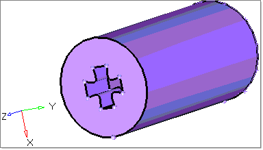
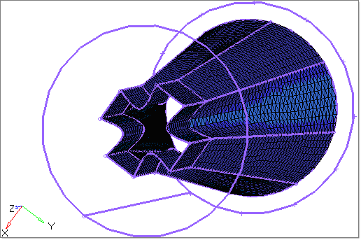
| 3. | In the Model browser, right-click on the Tool component and select Isolate. |
| 4. | Right-click on Plate3D and select Make Current. Right-click again and select Show. |
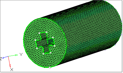
| 5. | From the main menu, select tetramesh. |
| 6. | Select the volume tetra subpanel for meshing. |
| 7. | With the solids button activated, select the Tool solid. |
| 8. | Set the element size to 1 mm and click mesh to create a tetramesh in the Tool component. The mesh is automatically moved to the Plate3D component. |
|
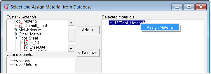
| 1. | To select and assign suitable materials, click Material Data on the Utility menu. |
| 2. | Select the material H_13(Tool Material) and click Add. |
| 3. | Right click on the selected material and click Assign Material. Assign the material to Plate3D component by clicking on the respective checkbox. |
| 4. | Set the Deformation type as Stationary Elastic and click Update. |
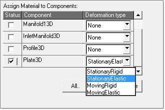
| 5. | Click Close to close the dialog. |
|
| 1. | In the Utility menu, under BCs click Create/Edit. |
| 2. | Click on BCs to create new boundary conditions. |
| 3. | In the Name field, enter Plate_SFI. |
| 4. | Set the Type: field to SolidFluidInterface and the Material field as H_13(Tool). |
| 6. | Enter the following boundary condition parameters: |
| • | Contact Type: Mismatched |
| • | Contact Surface: Manifold_SFI |
| • | Heat Transfer Coeff: 3000 W/m^2-degC |
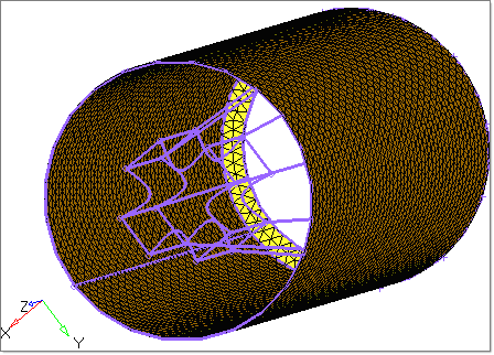
| 8. | Pick few elements in the interior face of the Plate3D component. |
| 9. | Repeat steps 2 through 4 to create another boundary condition named PlateOuter, with the following details: |
| 10. | Click Create to create the boundary condition. Keep the default parameters that appear and click Create Faces. |
| 11. | Pick few elements on the outer face of the Plate3D component and click proceed. |
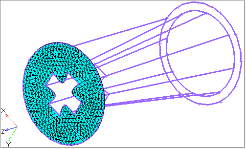
| 12. | Repeat steps 2 through 4 to create another boundary condition named PlateFree, with the following details: |
| 13. | Click Create to create the boundary condition. Keep the default parameters that appear and click Create Faces. |
| 14. | Pick few elements on the maximum Z face of the Plate3D component and click proceed. |
|
| 1. | Click Parameters in the Utility menu. |
| 2. | Click on the Polymer Processing tab and set the Free Surface start location field to 93 mm. |
| 3. | Click on the User Commands tab and write the commands solve and exit under Footer data. |
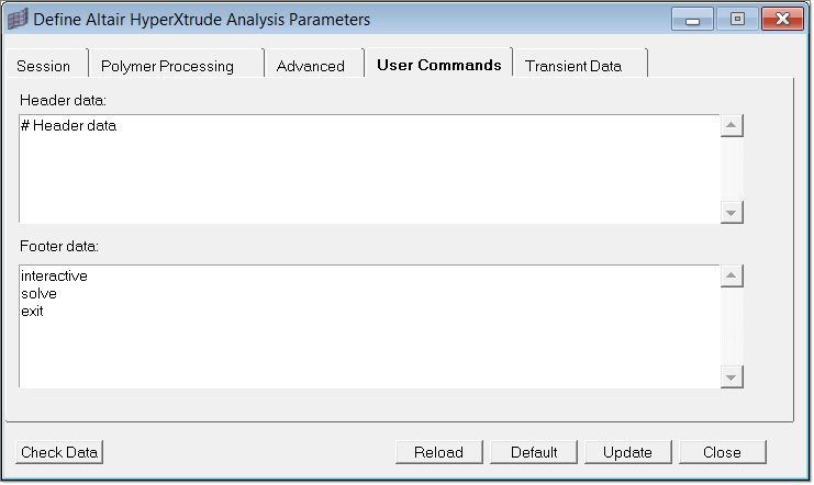
| 4. | Click Close to close the window. |
|
| 1. | In the Utility menu, click on Export/Launch Solver and set fields as shown in the following image: |
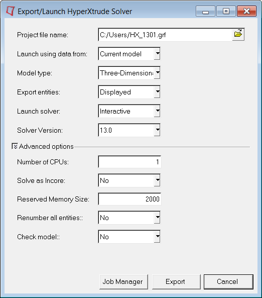
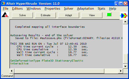
| 2. | Click on Export to launch the HyperXtrude solver in interactive mode. The data deck which includes HX_1301.grf, HX_1301.tcl and HX_1301_000.out files will be written into the specified project directory. |
|
Return to Polymer Processing Tutorials


