The model files for this tutorial are located in the file mfs-1.zip in the subdirectory \hx\MetalExtrusion\HX_1251. See Accessing Model Files.
To work on this tutorial, it is recommended that you copy this folder to your local hard drive where you store your HyperXtrude data; for example, "C:\Users\HyperXtrude" on a Windows machine. This will enable you to edit and modify these files without affecting the original data. In addition, it is best to keep the data on a local disk attached to the machine to improve the I/O performance of the software.
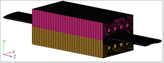
| 1. | Load the model HX_1251.hm. The model is already meshed. |
|
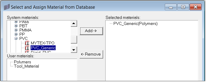
| 1. | To select and assign the suitable materials, click Material Data on the Utility menu. |
| 2. | Select the material PVC_Generic and click Add. |
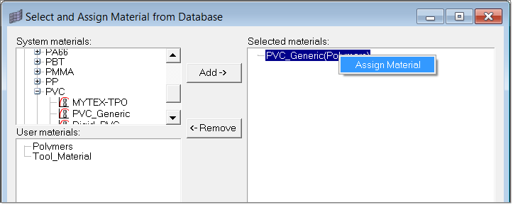
| 3. | Right-click on PVC_Generic and click Assign Material. |
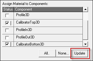
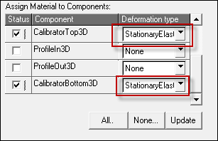
| 4. | Assign the material to suitable components by clicking on the respective component checkboxes. Click Update to complete the material assignment. |
| 5. | Repeat Steps 2-4 to assign the material H_13(Tool_Material) to the components CalibratorBottom3D and CalibratorTop3D. |
| 6. | Set the Deformation type as Stationary Elastic for components that have Tool Material assigned to them. |
| 7. | Click on Close to exit the Material Data window. |
|
| 1. | In the Utility menu, under BCs, click Create/Edit. |
| 2. | Click on BCs to create a new boundary condition. |
| 3. | Enter Inlet in the Name field. |
| 4. | Set the Type field to Inflow, and the Material field to PVC_Generic(Polymer). |
| 5. | Click Create to set the parameters for this BC. |
| 6. | Set the following fields, and leave the others with their default values: |
| 7. | Click Create Faces to assign the BC face elements for the BC. |
| 8. | Turn on the respective 3D component and pick one element on the face and click proceed. |
| 9. | Repeat steps 3 - 8 to create another boundary condition: |
Name
|
ProfileFreeBC
|
Type
|
FreeSurface
|
Material
|
PVC_Generic(Polymer)
|
| 10. | Click Create to set the parameters for this BC. Create another one, using the following parameters: |
Heat Transfer Type
|
Convection
|
Convection Coefficient
|
10 W/m^2-degC
|
Convection Temp
|
40 degC
|
| 11. | Pick a few elements on ProfileIn3D and ProfileOut3D to create ProfileFree BC. |
| 12. | Repeat steps 3 - 8 to create another boundary condition: |
Name
|
CalibratorOuter
|
Type
|
ToolSurface
|
Material
|
H_13 (Tool)
|
| 13. | Click Create to set the parameters for this BC. Use the following parameters: |
Heat Transfer Type
|
Convection
|
Convection Coefficient
|
10 W/m^2-degC
|
Convection Temp
|
40 degC
|
| 14. | Pick a few elements on the outer face of CalibratorTop3D and CalibratorBottom3D to create CalibratorOuter BC. |
CalibratorOuter BC
| 15. | Repeat steps 3 - 8 to create another boundary condition: |
Name
|
ProfileCalibrator
|
Type
|
SolidFluidInterface
|
Material
|
PVC_Generic(Polymer)
|
| 16. | Click Create to set the parameters for this BC. Use the following parameters: |
Friction Model
|
SlipVelocity
|
Frict Coefficient
|
100
|
Contact Type
|
Mismatched
|
Contact Surface
|
CalibratorProfile
|
Heat Transfer Coeff
|
3000 W/m^2-degC
|
| 17. | Pick a few element on the outer face of Profile3D. |
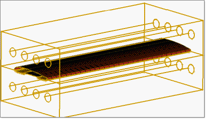
ProfileCalibrator BC
| 18. | Repeat steps 3 - 8 to create another boundary condition: |
Name
|
CalibratorProfile
|
Type
|
SolidFluidInterface
|
Material
|
H_13 (Tool)
|
| 19. | Click Create to set the parameters for this BC. Use the following parameters: |
Friction Model
|
SlipVelocity
|
Frict Coefficient
|
100
|
Contact Type
|
Mismatched
|
Contact Surface
|
CalibratorProfile
|
Heat Transfer Coeff
|
3000 W/m^2-degC
|
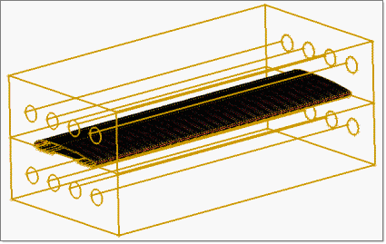
CalibratorProfile BC
| 20. | Repeat steps 3 - 8 to create another boundary condition: |
Name
|
Pipes
|
Type
|
ToolSurface
|
Material
|
H_13 (Tool)
|
| 21. | Click Create to set the parameters for this BC. Use the following parameters: |
Heat Transfer Type
|
Convection
|
Convection Coeff
|
1000 W/m^2-degC
|
Convection Temp
|
40 degC
|
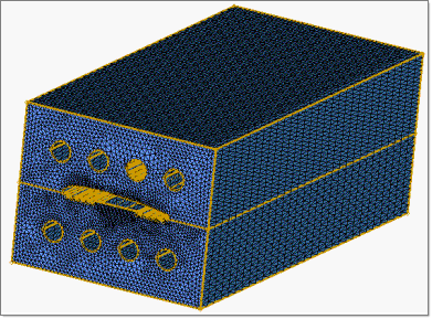
| 22. | Pick a few elements in the interior circular regions of CalibratorTop3D and CalibratorBottom3D. |
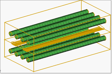
Pipes BC
| 23. | Repeat steps 3 - 8 to create another boundary condition: |
Name
|
Outlet
|
Type
|
Outflow
|
Material
|
PVC_Generic(Polymer)
|
| 24. | Click Create to set the parameters for this BC. Use the following parameters: |
Pressure
|
Checkbox should be activated
|
| 25. | Pick a few elements on the Maximum Z face of the Profile3D component. |
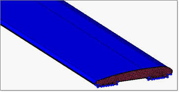
Outlet BC
|
| 1. | Click Parameters on the Utility menu. |
| 2. | Click on the User Commands tab and write the commands solve and exit under Footer data. |
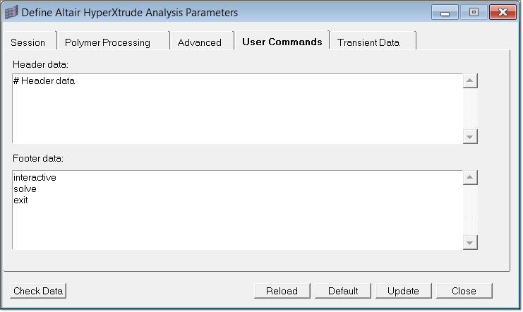
| 3. | Click Close to exit the Parameters dialog. |
The model setup is complete; it is ready to be exported and solved.
|
Return to Polymer Processing Tutorials


