The model files for this tutorial are located in the file mfs-1.zip in the subdirectory \hx\MetalExtrusion\HX_1202. See Accessing Model Files.
To work on this tutorial, it is recommended that you copy this folder to your local hard drive where you store your HyperXtrude data, for example, “C:\Users\HyperXtrude\” on a Windows machine. This will enable you to edit and modify these files without affecting the original data. In addition, it is best to keep the data on a local disk attached to the machine to improve the I/O performance of the software.
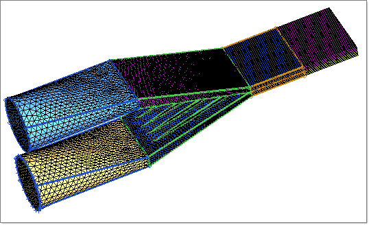
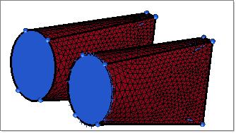
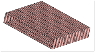
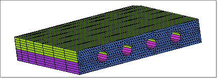
Load the model HX_1202.hm. The model is already meshed. In this analysis two polymers come together to form a part and enclose four copper wires. Hence, this is a coextruded part with metal inserts. This model, however, does not include the mesh for metal wires – this may be necessary if you are interested in computing any deflection of wire due to forces arising from the melt flow.
|
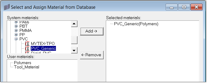
| 1. | To select and assign the suitable materials, click Material Data in the Utility menu. |
| 2. | Select the material PVC_Generic and click Add. |
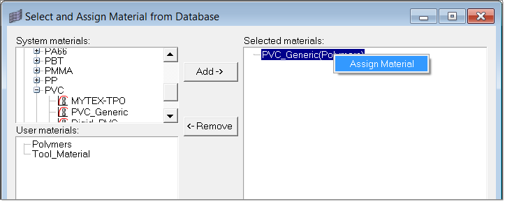
| 3. | Right-click on PVC_Generic and click Assign Material. |
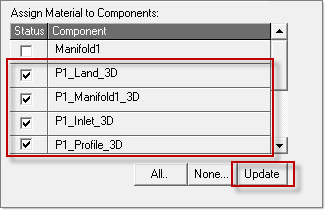
| 4. | Assign the material to suitable components by clicking on the respective component checkboxes. Click Update to complete the material assignment. |
| 5. | Repeat steps 1- 4 to assign the material PP_Generic to the components |
| 6. | Click Close to close the window. |
|
| 1. | In the Utility menu, under BCs click Create/Edit. |
| 2. | Click on BCs to create new boundary condition. |
| 3. | On the right side of the panel you will see the current boundary condition. Edit this panel to set the following conditions. |
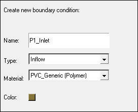
| 4. | Click Create to set the parameters for this boundary condition. Set the following data and leave the rest to the default values: |
| 5. | Click Update to save the data. |
| 6. | Click Create Faces to assign boundary condition face elements for this boundary condition. |
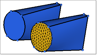
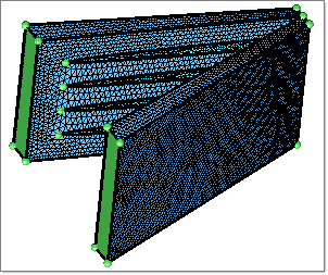
| 7. | In the Model browser, right-click on the Component folder and select Hide. Right-click on P2_Inlet_3D and P1_Inlet_3D and click Show. |
P1_Inlet
| 8. | Pick one element on the P1_Inlet_3D face and click proceed. |
| 9. | Click on BCs again to create another new boundary condition. |
| 10. | Set the following conditions. |
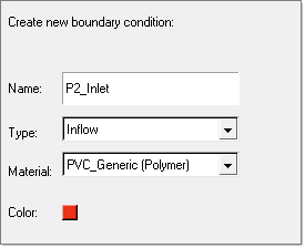
| 11. | Click Create to set the parameters for this boundary condition. Set the following data and leave the rest to the default values: |
| 12. | Click on Update to save the data. |
| 13. | Click on Create Faces to assign boundary condition face elements for this boundary condition. |
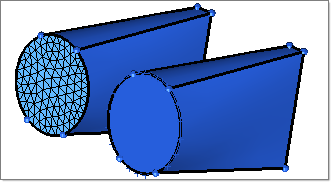
| 14. | Pick one element on the P2_Inlet_3D face as shown and click proceed. |
P2_Inlet
| 15. | Repeat steps 9 - 10 with the following data: |
| • | Material: PVC_Generic(Polymer) |
|
InletManifold_SFI
|
| 16. | Set Friction Model = Stick and click Update. Then repeat steps 13 - 14. |
|
| 17. | Repeat steps 9 - 10 with the following data: |
| • | Material: PVC_Generic(Polymer) |
| 18. | Set Friction Model = Stick and click Update. Then repeat steps 13 - 14. |
|
Manifold1_SFI
|
| 19. | Repeat steps 9 - 10 with the following data: |
| • | Material: PVC_Generic(Polymer) |
| 20. | Set Friction Model = Stick and click Update. Then repeat steps 13 - 14: |
|
Land
|
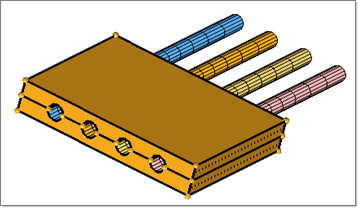
| 21. | Repeat steps 9 - 10 again to create four new boundary conditions with the following data used for all four: |
| • | Name: Wire1, Wire2, Wire3, and Wire4 |
| • | Material: PVC_Generic(Polymer) |
| 22. | Click Create and set the following: |
| • | Heat Transfer Type = Temperature |
| 23. | Pick one element on both sides of the interior face of the Wire geometry. |
|
|
| 24. | Repeat steps 9 - 10 with the following data |
| • | Material: PVC_Generic (Polymer) |
| 25. | Click Create and set the following: |
| • | Heat Transfer Type = Convection |
| • | Convection Coeff: 15 W/m^2-degC |
| • | Convection Temp = 40 degC |
|
|
| 26. | In the Model browser, turn on the display of P1_Profile_3D and P2_Profile_3D. |
| 27. | Pick one element on all of the exterior faces to create the FreeSurface boundary condition. |
|
| 28. | Repeat steps 9 - 10 with the following data |
| • | Material: PVC_Generic (Polymer) |
| 29. | Click Create and set the following: |
| 30. | Pick one element on the maximum z face of P1_Profile_3D and P2_Profile_3D to create the Exit BC. |
|
|
| 31. | Repeat steps 9 - 10 with the following data |
| • | Type: FluidFluidInterface |
| • | Material: PVC_Generic (Polymer) |
| 32. | In the Model browser, turn on the display of P1_Land_3D and P1_Profile_3D. |
| 33. | Pick a few elements on the common face for P2_Land_3D and P2_Profile_3D to create the P1_FFI BC. |
| 34. | Similarly, create P2_FFI boundary condition and select common face elements on P2_Land_3D and P2_Profile_3D. |
|
|
|
| 1. | On the Utility menu, click Parameters. |
| 2. | On the Polymer Processing tab, set the following parameters: |
Free Surface Start Location = 205 mm
Free Surface Relaxation Factor = 1
| 3. | Click the User Commands tab and write the commands solve and exit under Footer Data. |
| 4. | Click on Close to exit the Parameters window. |
|
| 1. | On the Utility menu, click on Export/Launch Solver and set the following. |
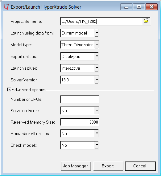
| 2. | Click on Export to launch the HyperXtrude solver in interactive mode. |
|
Return to Polymer Processing Tutorials


