The Die Structure Optimization process is a function used to automatically transfer tool contact forces from stamping analysis to a structural model and an easy step-by-step setup of die structure optimization model. The Die Structure Optimization process consists of two steps:
Exercise 1: Set up and Run Die Stress Analysis
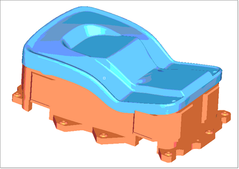
This exercise uses the model file DieStress.hf
Die Stress Analysis and Die Optimization features are under the Tools menu.
|
| 1. | On the toolbar, select File > Open and browse to the file DieStress.hf. |
Note: The model files for this tutorial are located in the file mfs-1.zip in the subdirectory \hf\ResultMapping\. See Accessing Model Files.
| 2. | From the toolbar, select Tools > Die Stress Analysis. |
The Create/Open Process Instance appears:
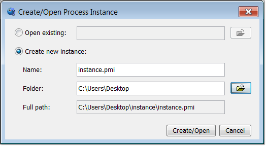
| 3. | For Folder, click  and indicate a directory to save the results of the analysis. and indicate a directory to save the results of the analysis. |
The Process Manager tab appears in the tab area. The Process Manager is a step by step approach to preparing and running Die Stress Analysis.
|
| 1. | In the panel area, Steel is shown as the default material in the Material field. Click Apply. |
Notice that the white check mark turns green for Tool Material in the Process Manager tab.
| Note: | Clicking on Apply at each step will turn the white check mark green in the Process Manager and a white check appears for the next option. |
|
| 2. | For the Result file field, select either RADIOSS or LS-Dyna as the stamping solver. |
| 3. | Click on Browse… and locate and load the results of the forming analysis. In this exercise you will use the file LawnMower2A001. |
| 4. | Click Apply. The Process Manager launches HyperView to query the model and create a list of components that are available in the stamping model. Once the results are brought back into HyperForm, you will be able to select which tool to extract the contact forces from. |
| 5. | For the Result part field, select Punch and click Apply. This is the tool from which forces are extracted at the last step of forming analysis. This will launch HyperView for a moment and will close on itself. |
| 6. | Click on Components: and select the skin of the Die component from the screen. This will be the part onto which the loads will be mapped. |
|
| 1. | In the Model Browser, click on the plus symbol next to LoadCollector to expand the tree. |
| 2. | Turn off the loads display by clicking on the mesh icon next to operational. |
| 3. | Expand the Components folder, and click on the mesh icon to display the Punch_solid component. |
|
| 1. | Click on the Process Manager tab. |
| 2. | Click on Nodes twice and select By Sets. |
| 3. | Select the Holding component. Notice that the bolt location nodes of the die are highlighted on the screen. |
| 7. | Click on Nodes twice and select Lift. Notice the set of nodes on the die gets highlighted on the screen. |
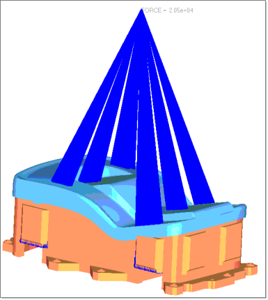
| 11. | Enter 1500 in the lifting height: field. |
| 12. | Click on Apply. This will create rigid elements connecting the nodes selected on the lifting location of the punch to the CG of the model, as shown below. |
| 14. | Click on Browse and select a location to save the file. Enter the name with a .FEM as the extension. |
| 16. | Click on Export to produce the input file. |
| 17. | Click on Export&Run to produce the input file and run stress analysis. |
Note:
| • | Make sure that all the steps on the Process Manager tree has a green tick mark which indicates that all the steps were successfully completed. |
| • | Stress analysis on the punch is done in the background. The results of the stress analysis will be the input for Die Structure Optimization. |
|
|
Exercise 2: Set Up and Run Die Structure Optimization
Die Optimization can be accessed from the Applications menu.
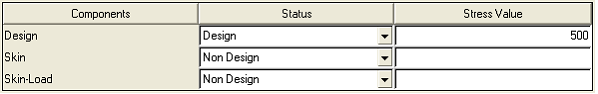
| 1. | Select the Design component under Status column, as shown in the figure below: |
| 3. | Enter 25.0 in the Min Member Size: field. |
| 4. | In the Draw Direction: list, select Z. |
| 6. | In the Volume Fraction: field, enter 0.3. |
| 8. | For Objective:, select Max Stiffness. |
| 10. | Next to the Export File: field, click on Browse and enter a file name with the extension .fem. |
| 12. | Click on Export to create the input file for optimization. |
| 13. | Click on Export&Run to create the input file and run the optimization. |
|
Return to HyperForm Tutorials


