In this tutorial, you will learn the procedure for mapping forming results onto structural models using the HyperWorks Results Mapper.
In real time practice, you may come across situation where the end results of formed parts have to be considered when it goes as a part of an assembly for structural analysis to depict a more realistic situation. To achieve this, HyperWorks Results Mapper is used.
HyperWorks Results Mapper (HWRM) is a HyperCrash based tool that provides a framework to initialize a structural model with results from a forming simulation. You will go through a simple procedure loading the structural model and forming simulation results followed by mapping the results and finally exporting the mapped data in a structural solver format. For output, the structural solvers currently supported are RADIOSS Y, RADIOSS STA, Abaqus and OptiStruct. The results are transformed as necessary if the forming and structural models are in different co-ordinate frames.
In this tutorial, you will first import the structural model and find a region on it which is almost similar to a region on the formed component. This region identification is the reference for the Results Mapper. Then, you will import the results of the formed component, identify the same region, and map the forming results to the structural model.
This tutorial assumes that you are familiar with HyperCrash. If you need help on these topics, please refer to the corresponding tutorials in the online help.
Results Mapper can be accessed by clicking Start > Altair HyperWorks > Manufacturing Solutions > Results Mapper.
Exercise: Mapping the forming data from a STA file onto a RADIOSS mesh
This exercise uses the models:
Note: The model files for this tutorial are located in the file mfs-1.zip in the subdirectory \hf\ResultMapping\. See Accessing Model Files.
| 1. | Click Start > Altair HyperWorks > Manufacturing Solutions > Results Mapper. |
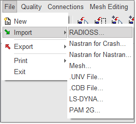
| 2. | In HyperCrash, click on File, then click Import and select RADIOSS, as shown in the figure below. |
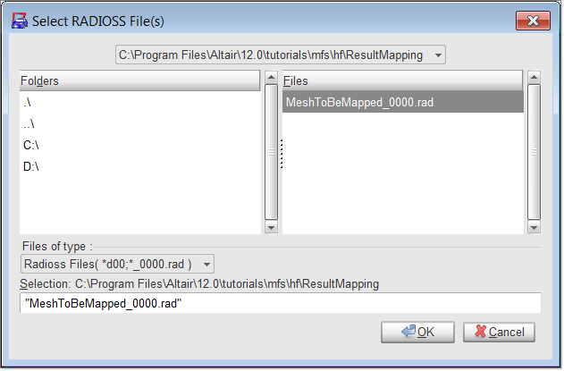
| 3. | Browse and locate the file MeshToBeMapped_0000.rad. Click OK to open the file. |
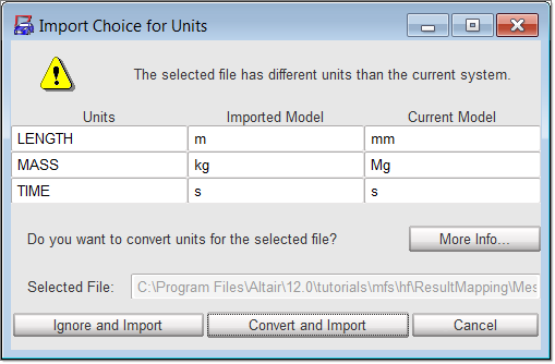
| 4. | The Import Choice for Units dialog is displayed. Click on Ignore and Import. |
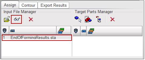
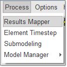
| 5. | Click on Process and then select Results Mapper from the menu, as shown below. |
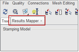
This will bring up Results Mapper inside HyperCrash as shown below.
|
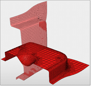
Upon loading the files, the STA file, which is in the forming coordinate system, and the target model, which is in the car coordinate system, appear on top of each other, as shown below:
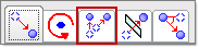
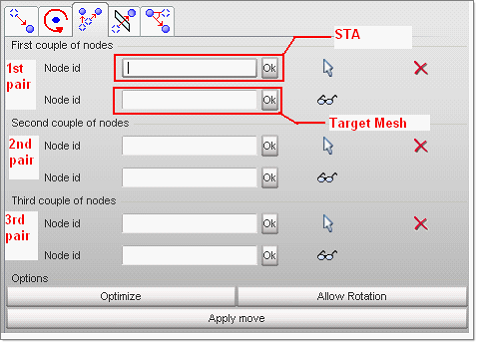
| 1. | Click on the Positioning button. |
| 2. | Click on the third option, as shown in the red box below: |
| 3. | Click on the arrow next to node Id below the header First couple of nodes. |
| 4. | Pick the first node on the horizontal model shown on the left hand side of the image below. |
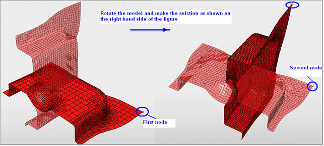
| 5. | Rotate the model by ~90 degrees (press and hold the Ctrl button and left mouse button, move the mouse to rotate) to make the second selection as shown on the right hand side of the image above. |
| 6. | Follow steps 4 and 5 to select 2 more corner node pairs as the second couple of nodes and the third couple of nodes. Refer to the image below: |
| 8. | Click on Allow Rotation. |
| 10. | Click on Ok in the bottom left hand corner to validate and accept the positioning. |
|
| 1. | Click on the include picked part icon  . . |
| 2. | Graphically select the structural model from the screen. The selected part name is displayed within the Results Mapper in the right hand column. |
| 3. | Click Yes on the right hand bottom corner of the screen. |
| 4. | Click on Map Results at the bottom of the Result Mapper. The results are mapped and are shown in the Results Mapper area. |

|
| 1. | Click on the Contour tab. |
At this point, you may need to expand the Results Mapper tab by dragging the right side bar further out. This will enable you to see the entire Contour tab of the Results Mapper.
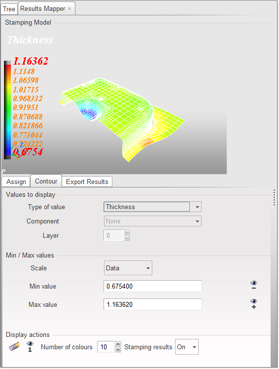
| 2. | In the Type of Value: field, select Plastic Strain from the drop down menu. |
Notice that the mapped data changes to Plastic Stain both for STA mesh and the structural mesh.
| 3. | Use the arrows in the On integration point: field to change the value in the box. Notice that the mapped result type is automatically updated with the new data. |
| 4. | Click on the Output tab. |
| 5. | Click on the Browse button. |
| 6. | Navigate and select the destination folder. |
| 7. | Type PlasticStrain.inp in the field and click on OK. |
| 8. | In the File Format field, select Abaqus. |
| 9. | Make sure the Thickness, Plastic Strain and Stress Tensor fields are checked. |
| 10. | Click on Export. The file is exported. |
|
Return to Result Mapping Tutorials