|
»Click here to display Table of Contents«
|

graphics subpanel |

|

|

|

|
|
graphics subpanel |
|
|
|

|
|
»Click here to display Table of Contents«
|
graphics subpanel |
|
|
|
|
|
graphics subpanel |
|
|
|
|
The graphics subpanel allows you to specify display options.
The following controls exist on the graphics subpanel:
lights |
The lights option allows you to set light-based shading to smooth, none, or flat. |
|||||||||
view simplification |
To produce smoother animation when rotating or panning a model, you can refrain the calculation and rendering of some model elements until the model stops moving. |
|||||||||
simplify current comp |
Used in conjunction with view simplification, this applies the simplification to the current component as well as the rest. Leave this unchecked to retain the full detail of the current component during view simplification. |
|||||||||
bitmap animation |
Bitmap animation allows you to render animation sequences as a series of 2-D images instead of full 3-D modeling. For large models this can produce faster animation, but for small ones it may actually produce slower results. |
|||||||||
AVI Options |
Use this switch to select the frame size of exported Audio-Video Interleave animation files, as a fraction of your screen size. Use the toggle just below the switch to choose the color depth to output AVI files in: 8 bit (256 colors) or 24 bit (16.8M colors). |
|||||||||
result color type |
Use this toggle to choose between blended contours and discrete contours. |
|||||||||
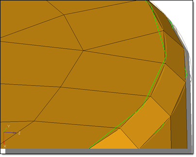
geometry refinement |
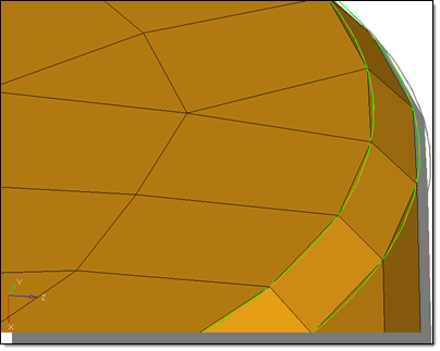
This option controls how extensively the graphics engine smooths faceted feature lines and contours within geometric entities such as lines and surfaces. Use the switch to select one of the six geometry refinement levels: Level 1, Level 2, Level 3, Level 4, Level 5, and Auto. The degree of faceting is arbitrarily numbered from 1 to 5, with 5 being the most refined and 1 being the coarsest. Higher values may affect rendering performance. If you do not want to continuously keep adjusting the degree of faceting, select Auto to automatically increase the geometry resolution when you zoom in on a model.
Lower refinement
Higher refinement |
|||||||||
element handle |
Elements are normally drawn as simple triangles or quads, but when this option is active each element also includes a small handle in its center, which can sometimes aid in selection of individual elements. However, handles are one more item for the graphics engine to render — so disabling them may improve rendering speed when working with large models. Next to the checkbox is a numeric box that accepts values from 0 to 10. This value filters out the text labels on element elements depending on how closely zoomed in the view is.
|
|||||||||
load handle |
Loads, such as Forces, Pressures, Moments, or Temperatures, normally display with a text label indicating the type (for example, "m" for moments) and the numeric magnitude. Clearing this checkbox will cease the drawing of any load labels.
|
|||||||||
geom handle |
The geom handles option allows you to specify whether or not to display line and surface handles. |
|||||||||
fixed points |
The fixed points option allows you to specify whether or not to display fixed points. This does not affect the display of free points. Fixed points can also be turned on and off from vis opts in the Geometry Cleanup panel. |
|||||||||
coincident picking |
The coincident picking option allows you to graphically select a desired entity from a stack of coincident entities when there are multiple entities at the same location. For example, if multiple loads are detected at the same location, a circular insert pops up containing various loads displayed separately with their IDs turned on. You can then pick the appropriate load. This function is activated by turning on coincident picking in the options panel. The entities supported for coincident picking are nodes, elements, loads and systems. |
|||||||||
template labels (type) |
This option allows you to display the element labels as template names (based on current user profile) or HyperMesh names. |
|||||||||
shrink |
The shrink setting controls the shrink factor to be used when drawing elements. With zero shrink, each element is drawn so that its corners directly connect to its nodes. If you specify a shrink value greater than zero, the element is scaled by the specified value about its centroid so that its corners do not appear to touch its nodes. The shrink value must be between 0 and 1. Shrinking elements is a useful for detecting holes in a mesh and improving wireframe element picking. |
|||||||||
Thick Mesh Lines |
Models with many different components may end up with some components being drawn in colors that do not contrast very well with the HyperMesh background. Activate this checkbox to draw mesh lines in double the normal width for better visibility of low-contrast colors. |
|||||||||
Thick 1D Elements |
Activate this checkbox to draw 1-D elements in double the normal width for better visibility.
|
Specify the view simplification method
Specify my bitmap animation preference