Sides Selection
When the sides selection toggle is set to auto sides selection, the surfaces to offset are automatically selected using the following rules:
| 1. | First, the surfaces adjacent to the manipulator ends are selected if the angle between the normal to the surface at the dimension end and the dimension direction is less than the max pick tilt value. |
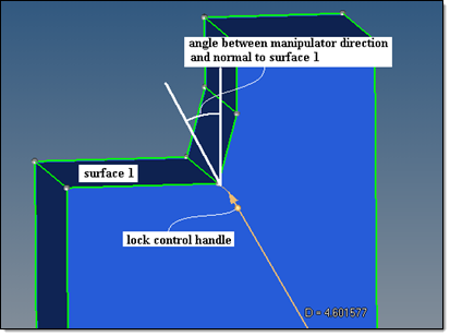
Angle between the normal to the surface and the manipulator direction.
If surfaces will be selected at both ends for the specified max pick tilt value, then the lock control handles will allow for manual manipulation of the offset scenario.
| 2. | Next, the surfaces adjacent to the selected surfaces are appended, provided that they are planar and the angle along the edge over which they are adjacent to the already selected surface is less than the max expand angle. |
| 3. | Finally, the total areas of the surfaces selected at each end are calculated. If the area of the surfaces selected at one side is more than the side selection area ratio times larger than the area of the surfaces selected at the other side, then the surfaces on the larger area side are unselected. In this case, only the surfaces at the smaller area side are used for offset. |
|
side selection area ratio = 3
|
side selection area ratio = 1.5
|
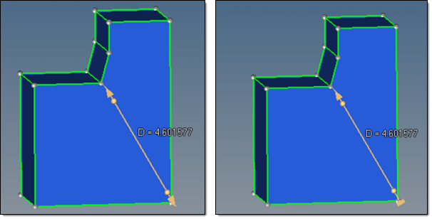
Bottom surface area twice as much as the top surface, so bottom will not move (note the lock indicator).
|
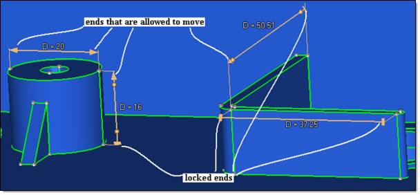
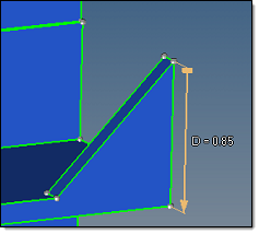
The ends of the dimension lines that are allowed to move are marked with arrows, while the locked ends are marked with blocks.
Examples of lock icons.
When both sides have surfaces that satisfy rule 1 above, rule 3 can be manually overridden. In this case the lock controls (spheres near the icons) define the offset scenario. Clicking the lock control handles will toggle the lock state between locked and unlocked for that end. If a lock control state is manually specified, then rule 3 is ignored for that manipulator and the side selection area ratio option no longer applies.
When the sides selection toggle is set to manual sides selection, the surfaces to offset are selected using the surfaces to move collector. The manual surface selection is then governed by the lock state of the manipulator ends.
| Note: | Out of the selected surfaces, only those that are linked to at least one of the manipulator ends by a continuous selection are actually used in the offset. |
|
With the manual selection, the use of separator lines is also available (see the surface edit offset subpanel for details).
Manual surface selection allows great flexibility. Take the model below, for example, where the 3 highlighted surfaces are selected to change the dimension from 50.5 to 70 and move the wall to a new position.
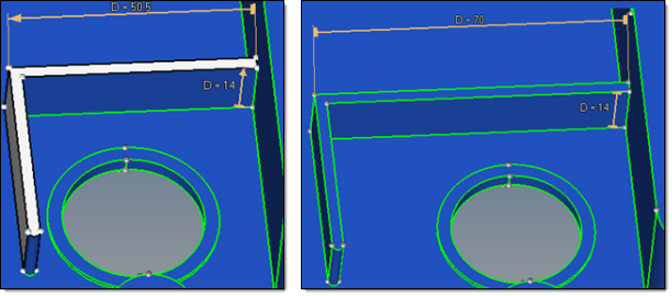
Dim 50.5 changed to 70 to move the wall.
The penalty of such flexibility is that if the surfaces are selected erroneously, the results can be unexpected or catastrophic. Due to this, save good results often and be ready to use the reject button.
Involved Surfaces Interpolation System
There are currently two interpolation methods available. The first is a local coordinate system (LCS)-based 2D interpolation and the second is a global coordinate system-based 1D linear interpolation.
The local method (LCS) "slides" along the surfaces to determine the offset vectors, which are then interpolated and combined into the interpolated offset at each point. Selected surfaces are always interpolated using this method
The global method (1D linear interpolation) uses a proportional stretching/compressing of a surface in global 1D. It is applicable only when all the offset vectors at the surface vertices are collinear and proportional to the distance parameter along their common direction.
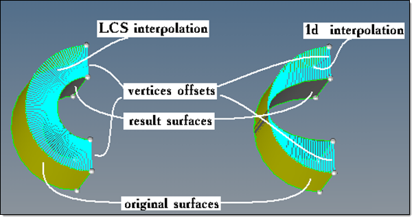
Interpolation of the same offset vectors at the vertices for both methods.
The automatic option exercises a heuristic algorithm that tries to decide individually for each applicable involved surface which of the two interpolation algorithms is expected from an engineering perspective.
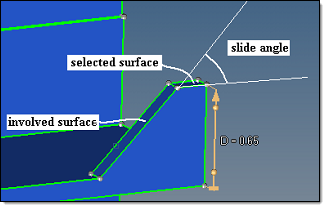
Slide Angle
When a selected surface is offset, the involved surfaces are modified to keep the continuity of the model. The two natural ways of doing this are "dragging" the involved surface behind the selected surface, or using it as a "slider" along which the selected surface slides. The determination of which method is used is controlled by the min slide angle option. If the slide angle is more than the min slide angle, the involved surface will slide; otherwise it will drag.
Original model
|
|
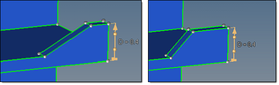
Involved surface dragged
|
Involved surface as slider
|
Dimension modified to D=0.4.
|
When the involved surface is a slider, the orientation of the surface does not change for planar surfaces. However, for curved involved surfaces, the sliding directions are defined by the tangents to the surface where it is adjacent to the selected surface. Sliding of the selected and involved surfaces along these directions may result in some change of the shape of the involved surface as well.
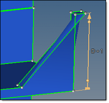
Removed Collapsed Surfaces
When enabled, the portions of offset surfaces that fold into themselves or adjacent surfaces (portions of surfaces that penetrate themselves or adjacent surfaces along the edges they are adjacent over) are removed.
For example, suppose that the slide angle is greater than the min slide angle and the value in the manipulator is set to 1. If this option is off, the involved surface will slide and ignore the self-penetration, resulting in a corrupt model. However, if this option is enabled, the involved surface will slide as far as possible without causing self-penetration. This may not allow the specified dimension to be reached, but will not result in a corrupt model.
|
|
Remove collapse surfaces off
|
Remove collapse surfaces on
|
Dimension modified to D=1.
|
Another useful application is for the removal of holes. If the hole diameter is set to 0 and this option is on, the hole will be removed. If the option is off, a small "straw surface" will still remain.
In general, unless it is known that collapsed surfaces will result, it is better to keep this option off for performance reasons, as this option has no affect on general cases that do not result in penetration.
See also
Dimensioning Panel
Dimension Manipulators
Advanced Considerations


