Manufacturing Solutions

Surface Edit panel

Surface Edit panel

Previous topic Next topic Expand/collapse all hidden text  

Surface Edit panel

Previous topic Next topic JavaScript is required for expanding text JavaScript is required for the print function  

User Profiles:

Incremental_RADIOSS

Incremental_LS-DYNA

RADIOSS One Step

Die Module

Use the Surface Edit panel to perform a variety of surface editing, trimming, and creation functions.  This panel also allows you to offset surfaces in their normal direction.

Note:The topology revision option in the meshing subpanel of the Options panel affects the behavior of Surface Edit panel. When this option is set to delete mesh, the surface editing tools will delete the elements associated to the affected surfaces.  For instance, if you want to trim surface with two nodes, the elements of the surfaces that are affected by this trim are deleted and then the surface is updated with the trim lines.  This option does not have any affect on the lines from surf edge function or the offset function.


Subpanels and Inputs


The Surface Edit panel contains the following subpanels:

expand-green-10Trim with Nodes

Allows you to trim (split) a surface using nodes.  The surface can be trimmed with two nodes, with multiple nodes, or with a node normal to and edge.

For a two nodes trim, you must pick two nodes that belong to a single surface.  HyperMesh automatically detects the surface that needs to be trimmed.  (If HyperMesh detects more than one unique surface to be trimmed, the trimming operation fails.)  The surface is trimmed by a projection of the line connecting the two nodes.  The projection is performed in the direction normal to the surface.

For a multiple nodes trim, HyperMesh creates a smooth line through the nodes selected (these nodes need not be part of the surface that is selected to be trimmed) and then trims the selected surfaces with projection of this line along the surface normal.  These trimming operations can split the surface into multiple surfaces if the line cuts the entire surface.

For a node normal to edge trim, you must pick a node and a surface edge.  HyperMesh splits/trims the surface along a straight line which is perpendicular to the selected edge and connects the edge to the selected node.


Panel Input

Input

Action

two nodes: node selector

Pick the first and second node on a single surface. The surface operation is performed after you select the second node.

multiple nodes:  surfs selector

Pick the surface to trim.

multiple nodes: node list

Select the nodes that define the line you want to use to trim the surfaces.

node normal to edge: node selector

Select the node to begin the trim operation.  The surface is split along a vector that passes through this node perpendicular to the selected line.

node normal to edge: lines selector

Select the line to begin the trim operation.The surface is split along a vector perpendicular to this line that passes through the selected node.


expand-green-10Trim with Lines

Allows you to trim/split surfaces using a line (or a group of lines).  There are three methods of doing so:

Trim with a cut line: you can drag or draw a line across the screen to define where you wish the cut to be made.
Trim lines: lets you sweep existing lines to surfaces, effectively projecting a copy of the selected line to the selected surface and trimming it.  For example, this allows you to use a circular line currently offset from the surface to create circular holes in the surface.
With offset line: This lets you select existing lines on a surface and create offset or scaled copies of them to trim the surface.


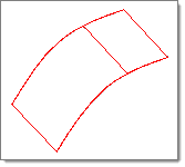
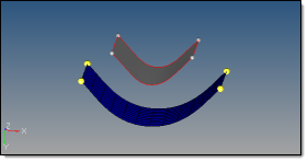
Trimming a selected surface(s) to a line involves sweeping a line along a vector to create a temporary surface, and trimming the selected surface(s) with the temporary surface.  You can use the entire surface/distance = toggle to set the distance the line is swept, or use a calculated distance that trims the entire selected surface(s).  If the temporary surface does not intersect the selected surface(s), an error is reported.  When a surface is trimmed, it is actually broken into smaller pieces (surfaces).  After the surface is trimmed, you can delete any unwanted surfaces.


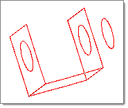
Example: Trimming a Surface with Lines

HM_Panels_bmp00340

Before trimming. Surfaces are selected.

HM_Panels_bmp00341

Entire surface is trimmed with the line.


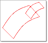
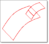
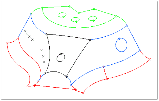
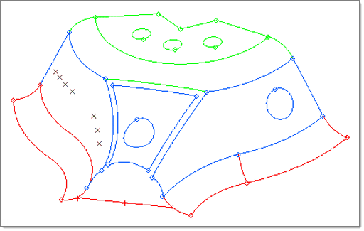
Example: Trimming a Surface with Offset Lines

surface_edit_trimline_offsetline_1

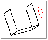
Here, only the outer rectangular surf and the circular line are selected.

Panel Input

Input

Action

with cut line: surfs selector

Pick the surface to trim.

drag a cut line

Click this button to graphically create a dragged line to cut the surface. A line stretches dynamically between the first point selected, and the current location of the mouse pointer.

smooth line

Creates a curved line that passes through the points you specify

close line

Creates a closed loop, automatically connecting the first and last points that you specify.

with line: surfs selector

Pick the surface to trim.

with lines: lines selector

Pick the line you want used to trim the surface on your model.

The following types of lines can be selected:

free lines (default).  Only select free lines.
surf edges.  Only select surface edges.
lines.  Select any type of line.

along a vector / normal to surface

Select normal to surface to trim the surface directly "under" the line, as if the line were a new surface that intersects the selected surface perpendicularly.

Select along a vector to specify the angle from the line to the location of the new surface split, as if the line were a surface concurrent with the specified vector.

entire surface / distance

Choose between trimming the entire surface, or trimming only a user-specified distance. If you choose to use a specific distance, specify it in the distance = field.

vector selector

Select the vector coordinates.

keep line endpoints

Retain the line’s end points as fixed nodes on the trimmed surface

all attached surfaces / selected surfaces

All attached surfaces creates a new offset trim line in each surface that the selected line connects to.

Selected surfaces allows you to specify which surfs you wish to trim.

offset

Specify the offset.  The resulting additional lines will be generated this distance from the selected ones.

select closed loops

This checkbox will automatically select enclosed chains of line segments when picking lines.  Otherwise, only the line segments specifically clicked will be selected.


expand-green-10Trim with Surfs/Plane

Allows you to trim or split surfaces with another surface or a plane. This function determines the intersection of the selected surfaces and a plane or a surface, and then trims the original surfaces at this intersection.

When surfaces are trimmed, they are broken into smaller pieces (surfaces). After the surfaces are trimmed, you can delete any unwanted surfaces.


Example: Trim with Planes

HM_Panels_bmp00344

Surfaces are selected

HM_Panels_bmp00345

Surface is trimmed.


Example: Trim with Surface

HM_Panels_bmp00346

In this example, the smaller surface will be trimmed.

HM_Panels_bmp00347

Surface is trimmed.


Panel Input

Input

Action

with plane: surfs selector

Pick the surface to trim.

When trim with planes is active, a fill cuts mode is available. This mode is turned off by default. Select the fill cuts check box to turn it on.

vector selector

Select the vector coordinates.

fill cuts

Activates a special mode of surface trimming. A virtual trimmer surface is created and used to calculate and create new edges on selected surfaces. An attempt is made to insert pieces of this trimmer surface into the body when trimming of the trimmer itself by selected surfaces creates closed loops and thus cuts off those pieces. This is used to simulate solid trimming in cases when you cannot, or do not want to, create solids, but still wants to make solid-like cuts. 
 
This mode is not intended when selected surfaces are solid surfaces themselves. When attempting to insert pieces of a trimmer surface into a solid body, you may also need to manually select other surfaces in order to avoid topologically invalid results. If you do not make this selection completely correctly, the expected result will be undefined. 

with surfs: surfs selector

Pick the surface to trim.

trim both

Activate this check to have both surfaces trim each other.

extend trimmer

When this option is active, the trimming operation extends beyond the boundaries of the nodes, or lines that you used to define it.

Only available when trim both is inactive.

self-intersecting surfs: surfs selector

Pick the surface to trim. Every selected surface is trimmed at their intersections with each other.  This is very similar to using the trim both option when trimming with surfs, except that you simply select a single mass of surfaces and HyperMesh sorts them all out and trims each one whenever it intersects any other selected surface.

This feature is useful when dealing with cases such as a grid of intersecting surfaces.  Using the intersecting surfaces trim option allows you to separate all of the intersecting surfaces into multiple smaller surfaces with a single action, instead of having to trim them in pairs.


expand-green-10Untrim

Allows you to remove trim lines so that the trimmed surfaces return to their previous, untrimmed state.


Panel Input

Input

Action

at cursor: edge

Will remove a single, specific trim line.

surface_edit_untrim_basemodel

standard_arrow_beforeafter

surface_edit_untrim_at_cursoredge

Here, clicking each of the circular trim lines (holes) removes the trim and extends the surface.

all trim lines of surfs: surfs selector

Will remove all of the trim lines on one or more surfaces that are selected.

surface_edit_untrim_basemodel

standard_arrow_beforeafter

surface_edit_untrim_all_linesofsurfs_after

Here, picking the front face surface trims all of its lines, including the one forming the hole in its center.

Selected trim lines of surfs: lines

Use this selector to pick specific trim lines so that you can untrim portions of the surface.

surface_edit_untrim_before

The arrows indicate edges picked.

surface_edit_untrim_after

Each selected edge us untrimmed

Selected trim lines of surfs: shortcut/ extend

This determines how the surfaces are untrimmed.

shortcut generates a straight line between vertices.

surface_edit_untrim_before_shortcut

standard_arrow_beforeafter

surface_edit_untrim_after_shortcut

extend attempts to follow existing geometry by extending the edges using adjacent edges as a guide.

surface_edit_untrim_before_extend

standard_arrow_beforeafter

surface_edit_untrim_after_extend

Selected trim lines of surfs: keep vertices

When checked, the points denoting vertices remain even after untrimming.

internal trim lines: lines selector

Will remove one or more trim lines inside the boundaries of the surface selected.

surface_edit_untrim_basemodel

standard_arrow_beforeafter

surface_edit_untrim_internaltrimlines_after

Here, clicking each shared edge line removes it, stitching the adjacent surfaces.


expand-green-10Offset

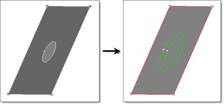
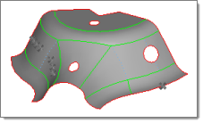
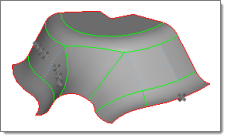
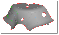
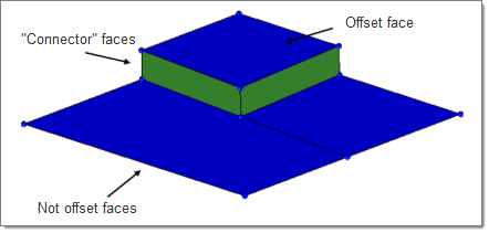
This subpanel can be used to offset a group of surfaces by a given distance along the normals of those surfaces.  A negative offset value can be used to offset these surfaces in the opposite direction of the surface normal.  The topology of the surface edges (free, shared edges, and so on) is maintained during the offset function.  Some individual surfaces will be trimmed or extended to maintain the connectivity.  This function moves the selected surfaces to the new location.

If you want to save the original surfaces, the selected surfaces can be duplicated (using the extended entity selected popup window) before the offset.  You can review the normal direction of the surfaces by clicking vector normal or color normal.  If the offset direction is incorrect, the reverse normal function can be used to reverse the normal of a selected surface.  If there are elements associated to the offset surfaces, the element will not move along with surfaces.  The association between the elements and their surfaces is broken.

There are two major types of offset: disjointed and continuous.  Disjointed offsets move the selected surfaces without retaining their connections to surrounding geometry, while continuous ones will either morph surrounding geometry to maintain connectivity, or create new surfaces to do so.


Examples

surface_edit_offset_start

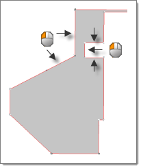
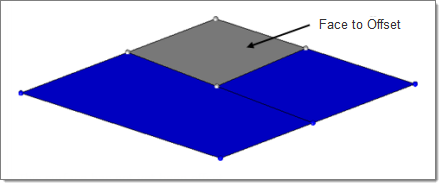
This surface has not yet been offset.

surface_edit_offset_disjoint

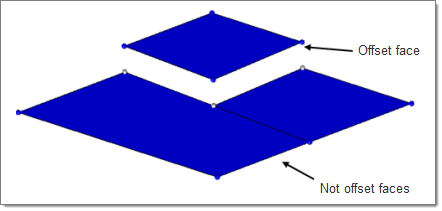
This is a disjointed offset.

surface_edit_offset_continuous_noseparators

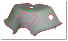
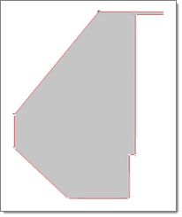
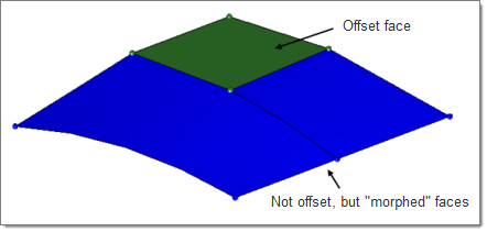
This offset uses the "continuous" option.

surface_edit_offset_continuous

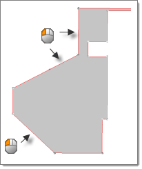
This offset uses the "continuous" option, with separator lines specified at the edges of the offset surface.


Panel Input

Input

Action

disjoint offset / continuous offset

A disjoint offset simply moves the surface, completely breaking its continuity with anything that it might previously have been in contact with.

A continuous offset creates new surfaces to connect the surface at its new position with lines that you specify, or morphs any surrounding/attached surfaces to meet the offset surface if no separator lines are chosen.

update eccentricity

This value is stored internally, and can be used later by the Midsurface Thickness Map utility.  It will not affect the movement of the offset surface; instead, the surface's associated thickness and offset values will remain in its original location, but be given values relative to its new location.  Later, these values can be used in the midsurface thickness utility to map its thickness and offset to FE elements.

remove degenerations

Degenerations are surfaces that become collapsed or unnecessary as a result of the offset.

autocomplete separators

This option automatically selects all segments of a closed loop of lines when you select any single line within the segment.

surfs selector

Select the surface to offset.

separator lines: lines selector

Indicate where the offset surface should remain attached; new surfaces will be generated to keep the surface continuous.

offset =

This can be a positive or negative number.  If you are uncertain where the positive normal direction lies, use the vector normal or color normal buttons to display it, and reverse normal if necessary/desired.

Note:The edges of a surface are offset in the normal direction, so curved surfaces may expand or shrink when offset in either the positive or negative direction--the surface dimensions are not preserved.

surface_edit_offset_curved


expand-green-10Extend

This subpanel extends or retracts the edges of selected surfaces to meet other selected surfaces, or to close gaps between surfaces or holes within a selected surface.

Several options affect how surfaces extension behaves, including enabling or disabling the ability to shorten edges as well as extend them, or to force the extended edges to attempt to maintain the overall shape of the surface.


Panel Input

Input

Action

max extension / extend over edges

Max extension: extend the surface using a maximum extension distance.

Extend over edges: extend a surface over edges to another surface

to surfaces

This choice is available when Extend over edges is selected.  The extending surfaces will extend as far as necessary to meet these ones.

by distance / by thickness multiplier

For by distance, type in the maximum distance that you wish the surfaces to extend.

For by thickness multiplier, type in the multiple of the surfaces' assigned thickness that yields the maximum distance you wish the surfaces to extend.

by filling gaps / by distance / to surfaces

by distance: This is the literal distance that selected edges will extend, measured in the same units that the model was created for.

by filling gaps: extends the edges of the hole to fill the gap.

surfs: to extend selector

Use this selector to pick only the surfaces that you wish to extend.

If you selected any shared (green) or non-manifold (yellow) edges as lines: to extend over, then this selector allows you to specify the corresponding surfaces so that Altair HyperWorks knows which surface to use to determine the plane of extension for the shared/non-manifold edge.

Additionally, you may need to use use this selector to specify any "target" surfaces, particularly if you use the cross extension option described below.  Edges will only extend toward surfaces that are also selected, even if those additional surfaces have no extending edges.  These recipient/target surfaces will also be trimmed, if the trim result surfaces checkbox described below is active.

cross extension / surfs: to target selector

cross extension allows for all input surfaces to be used as both extension and target surfaces. This is useful for doing bulk extensions where all selected surfaces should extend to others within the selection. The input surfaces will not extend beyond the specified max extension distance, nor will any of their edges extend if there are no other surfaces within the max distance.

When selecting this option for extending a surface over an edge, then all selected surface/edge combinations will be extended or shrunk.  Despite the name, in this case the surfaces will not cross through each other; having selected to surfaces ensures that they will meet rather than intersect.

surfs: to target simply extends the surfaces toward other surfaces.  You must use this selector to pick the destination surfaces; the extended surfaces will then extend up to the specified distance to meet those surfaces.  If the target surfaces are too far away, no extension occurs.

When using the surfs: to target option, you can select surfaces already selected as surfs: to extend.  Selecting the same surfaces in both surfs: to extend and surfs: to target produces the same result as the cross extension option.

When selecting this option for extending a surface over an edge, then the surfs: to extend that you have selected edges for in lines: to extend over will extend toward the surfaces that you select with the surfs: to target selector.  The target surface does not need to be selected as an extending surface.

lines: to extend over

Pick the edges that you wish to extend. The surfaces will be extended across these lines.  If you select a free edge, this also selects and highlights the corresponding surface.

surfs: to extend

Pick the surfaces that you wish to extend.

surfs: to target / cross extension

Extended surfaces will extend in the direction of surfaces selected in surfs: to target.

If cross extension is selected, all the selected line and surfaces will be extended.

trim result surfaces

If the checkbox is on and all selected surfaces extend or shorten to have their edges meet, then the selected surfaces will be trimmed or stitched regardless of which components they belong to.  If the checkbox is off, the result varies further:

If the selected surfaces are in the same component, they will not be trimmed but they will be stitched.  This is the default stitching behavior for surfaces in the same component.
If the selected surfs are in different components, they will not be trimmed or stitched.  This is the default stitching behavior for surfaces in different components.  If you need them to be stitched, you must do so by way of edge equivalence (or some other edge editing).


If the checkbox is on and the selected surfaces extend through their target surfaces, or even merely to the interior without actually touching any of the target surface edges, the surfaces will be both trimmed and stitched at the intersection regardless of whether or not they belong to the same component.  However, if the checkbox is off, the surfaces are not trimmed or stitched, since they do not meet at any edges.


expand-green-10Shrink

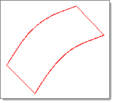
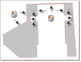
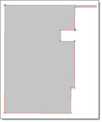
Shrinks the surface by drawing all of its edges (including internal edges from holes, and so on) "back" away from their starting location.

For example: if you shrink a square surface that has a circular hole in the center, the square would become smaller but the circular hole in its center would become larger, because the edge of the hole draws "backward" (that is further into the surface).


Example:

shrink_surface_selected

The black surface has been selected.

shrink_surface_shrunk

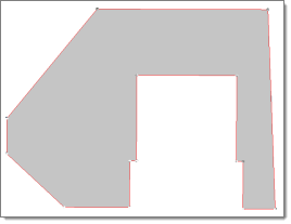
The edges of the selected surface pull inward, away from the initial edge locations.


Panel Input

Input

Action

surfs selector

Select the surfs to shrink.

offset

This is the distance that each edge of the surface moves further into the surface.

Note:Holes in the surface will get larger, not smaller, as their edges move further into the surface instead of out into the empty space bounded by the hole.


See also

Alphabetical List of Panels