This subpanel creates solids by interpolating smoothly between surfaces.
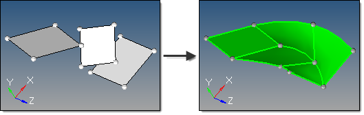
Five inputs are required to create a solid using this method:
| • | The surface list to use. A smooth interpolation is used between each pair of surfaces in the selection to create the solid. Multiple surfaces at the same level can be selected, as long as the selection order between different levels is not mixed. |
| - | Solid faces may be selected as input. |
| • | The create ring solid option specifies whether the first and last surfaces in the list should be considered as a pair in order to form a closed loop solid. |
| • | The split solid at shared surfaces option specifies how the resulting solid is split. If enabled, the solid is split at each of the input surfaces to create multiple solids with shared surfaces. If disabled, a single solid is created without shared faces. |
| • | The create in method, which defines the resulting solids component organization. |
| - | Specifying the current component organizes the new solids and the selected surfaces to the current component. |
| - | Specifying the surfs component adds the new solids to the same component that the selected surfaces already belong to. The result is unpredictable if surfaces from different components become a part of the same solid. |
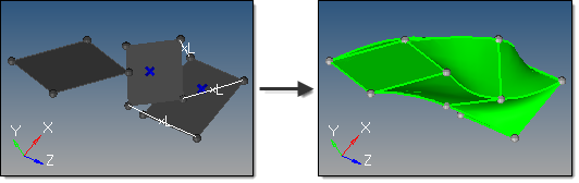
| • | The link type option determines whether user-defined links are used to provide better interpolation and shape control. |
| - | When set to default, any user-defined links or guiding lines/surfaces are ignored. |
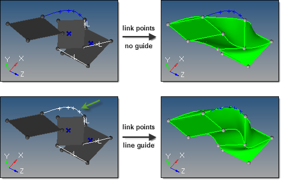
| - | When set to define links, node/point links can be defined. Node/point links are input as pairs since a link between input surfaces is specified by its two end points/nodes. Furthermore, a pair may not skip any surface in between. For instance, if surfaces 1, 2, 3 and 4 are defined in that order as the input surface list, a link can be defined from surface 2 to 3 but not from surface 2 to 4. If such a link is detected, it is ignored. One point/node may be linked to multiple points/nodes, which results in the creation of triangular surfaces. Node/point links show graphically as a white line between the pairs, with an L at the line center. To disable a pre-defined link, right-click the L graphic. To re-enable a disabled link, left-click the L graphic. |
| - | In addition, guiding lines and guiding surfaces can be defined when define links is selected. |
| - | Guiding lines are used to indicate part of the boundary of the final interpolated solid. If more than one guiding line is selected, the edges of the solid between these lines are obtained by smoothly interpolating the lines. If a guiding line extends beyond the input surfaces, that part of the line is ignored. |
| - | In order for guiding lines to be valid, they must: |
| a) | Connect the input surfaces at their boundaries. |
| b) | Connect to all intermediate input surfaces. |
| - | In order for guiding surfaces to be valid, they must: |
| a) | Link the step surfaces as a single-piece surface. In other words, if edge-A of a step surface is linked to edge-B of a step surface the linking surface must be a single surface. |
| b) | Be stitched to the edges of step surfaces. |
| c) | Link all the level surfaces of the solid. For example, if there are 3 step surfaces and one wants to use guiding surfaces, it is not enough to link only bottom and middle surfaces by a guiding surface. One needs to link the middle and the top surface also. |
| d) | If two or more guiding surfaces are located next to each other, they must be stitched together properly. |
| - | If any conditions are not met, those guiding lines/surfaces will be ignored. |
In the case of a surface with a scratch, if one of the internal points of the scratch is not linked to another surface at its boundary, this scratch is treated as if it is not part of the boundary, that is, as if it does not exist. If the scratch is linked upward but not downward, then is it considered a part of the boundary while constructing surfaces between its level and the level above, but it is ignored while constructing boundary with the surface below.
All the surfaces at each level must have the same number of internal loops, if any. Currently, only one internal loop at each level is supported. Cases with more than one internal loop will generate solids, but the matching between loops may not be desirable.


