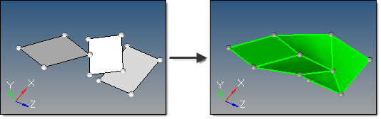
This subpanel creates solids by interpolating linearly between surfaces.
Five inputs are required to create a solid using this method:
| • | The surface list to use. A linear interpolation is used between each pair of surfaces in the selection to create the solid. Multiple surfaces at the same level can be selected, as long as the selection order between different levels is not mixed. |
| - | Solid faces may be selected as input. |
| • | The create ring solid option specifies whether the first and last surfaces in the list should be considered as a pair in order to form a closed loop solid. |
| • | The split solid at shared surfaces option specifies how the resulting solid is split. If enabled, the solid is split at each of the input surfaces to create multiple solids with shared surfaces. If disabled, a single solid is created without shared faces. |
| • | The create in method, which defines the resulting solids component organization. |
| - | Specifying the current component organizes the new solids and the selected surfaces to the current component. |
| - | Specifying the surfs component adds the new solids to the same component that the selected surfaces already belong to. The result is unpredictable if surfaces from different components become a part of the same solid. |
| • | The link type option determines whether user-defined links are used to provide better interpolation and shape control. |
| - | When set to default, any user-defined links or guiding lines/surfaces are ignored. |
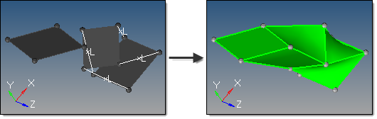
| - | When set to select links, node/point links can be defined. Node/point links are input as pairs since a link between input surfaces is specified by its two end points/nodes. Furthermore, a pair may not skip any surface in between. For instance, if surfaces 1, 2, 3 and 4 are defined in that order as the input surface list, a link can be defined from surface 2 to 3 but not from surface 2 to 4. If such a link is detected, it is ignored. One point/node may be linked to multiple points/nodes, which results in the creation of triangular surfaces. Node/point links show graphically as a white line between the pairs, with an L at the line center. To disable a pre-defined link, right-click the L graphic. To re-enable a disabled link, left-click the L graphic. |