Loose Shrink Wrap Mesh
Loose wrap wraps the selected elements or components, surfaces, or solids with the target element size specified, and outputs an outer-volume mesh which approximately adheres to the original FE topology.
A smaller element size generates a shrink wrap mesh that more closely approximates the original FE representation and adheres to more features; a larger element size produces a more basic mesh which ignores more features. The loose wrap does not project the nodes of the shrink wrap mesh to the original mesh, and typically the shrink wrap mesh will have an offset from the original mesh, again, the offset is dependent on the target element size used.
Once the shrink wrap meshing process has completed the new elements will be created in the current component. For every new run of the shrink wrap mesh, both loose and tight, it may be necessary to create a new component collector if you wish the elements to be placed in another collector other than the current component collector.
Comparison of Varying Mesh Sizes (Shell Output)
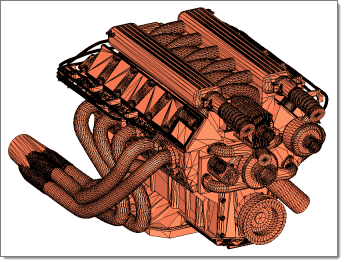
Figure 1. Original .stl Model
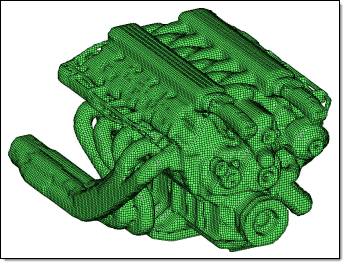 Figure 2. 2mm Mesh |
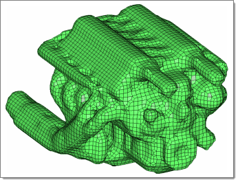 Figure 3. 5mm Mesh |
Comparison of Altering the Jacobian Value for Solid Mesh Generation
Figure 4. Original .stl Model
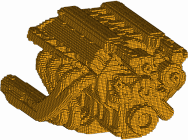 Figure 5. 2mm Solid Mesh, Jacobian=1.0 |
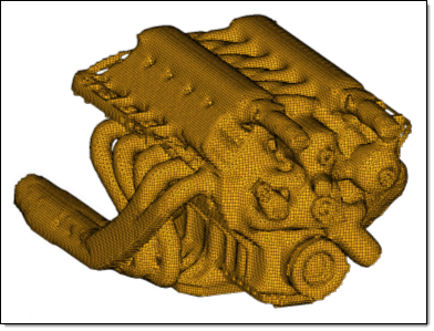 Figure 6. 2mm Solid Mesh, Jacobian=0.3 |
Shrink Wrapping with Feature Recognition
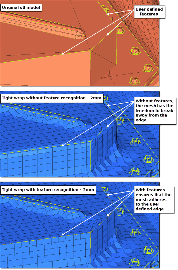
Figure 7. Shrink Wrap with and without Feature Recognition – 2mm
Comparison of using Global and Local Systems for Mesh Orientation
There is also an advanced option to control the mesh orientation. If you have a non-uniform part and you want to re-orientate the mesh so that it follows the features of the original component better then you can use this option. By default the mesh orientation always adheres to the global system, however, you can generate a local coordinate system and override the default behavior.
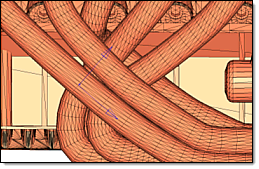
Figure 8. Original .stl Model
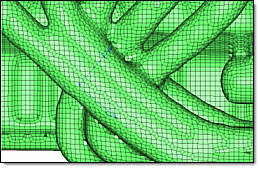 Figure 9. Shrink Wrap Output using Global System. Default shrink wrap mesh using the global system. |
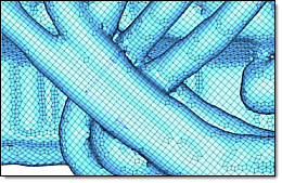 Figure 10. Shrink Wrap Output using Local System. Rows of elements in the reoriented mesh run along the tubes rather than at angles across them. |