Offset Bar2 Elements
Use the 1D Mesh: Offset tool to manually set offsets or adjust beams on plates.


Figure 1.
-
From the Mesh ribbon, click the 1D Mesh > Offset tool.

Figure 2. - Select the elements in the model you want to offset.
- Optional:
On the guide bar, click
 to define offset options.
-
Select an offset method using the options in the microdialog.
Option Description Offset on Plates Automatically offset a beam element. A bar2 element can be connected to either a single element's edge or can be shared between two elements at a plate T-junction. The Adjust to shell tool will consider a shell's thickness and offset during offset calculations. In the event of a sharp angle or T-junction, you can position the beam in four different quadrants.
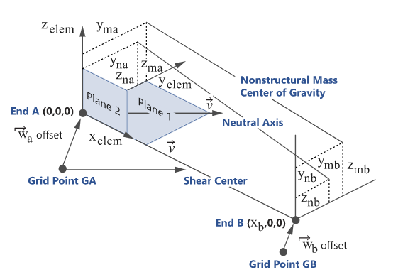
While performing an offset, you can choose whether the adjustment is done on both normal and lateral directions. A normal offset means that the offset is along the element's Y axis, while a lateral offset is along the element's Z axis. In the case of a free edge or T-junction, the beam is adjusted such that its bounding box matches with the edge.
Similar to the Orient context, options determine which shells are considered during the adjustment. They also handle thickness variations between adjacent plates. If the Thickness method option is not set to Averaged, the shell with the minimum (resp. maximum) thickness is used as a reference and adjustments are performed on this shell element.
- Click
 .
. - Use the drop-down menu below to choose the direction of adjustment. This can be either Normal and Lateral, Normal, or Lateral.
- Select the appropriate quadrant from the following:
- Positive base and adjacent
- Negative base and positive adjacent
- Positive base and negative adjacent
- Negative base and adjacent
Elemental YZ Manipulator Use the elemental YZ manipulator as an incremental offset manipulator in elemental systems. The elemental YZ manipulator acts on the whole selection of beam elements. Each manipulation along the Y or Z-axis will append that amount to every selected element regardless of their current offset value. This tool is not meant to assign the same resulting offset value to all selected elements. Instead, the selected elements will be updated by the exact same increment.
- Click
 .
. - Use the Y and Z manipulators to manually adjust the offset.
- PressEsc to return to the Offset context.
Offset Components Fine tune offsets by components. You can fine tune offsets in both the displacement system and the elemental system. Typically this is done when you need to update a large selection of elements.
- Click
 .
. - Enter the appropriate X, Y, and Z offset values and press Enter.
Reset Offset Click  .Note: This is not an Undo operation. Reset will always set to 0,0,0 regardless of previous value.
 - Click