Overview
An introduction to composites terminology and modeling methods.
Terminology
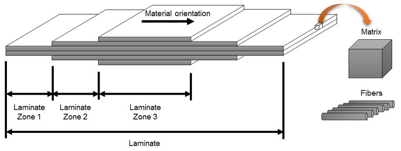
Composite modelings terminology.
- Laminates are made by stacking plies in a given sequence
- Plies are made up of two or more constituents (typically fiber/matrix)
- Laminate zones are areas of constant thickness within a laminate
- Reference orientation defines the common orientation fiber directions are rotated from

Figure 1.
Modeling Methods
Composite modeling methods.
Shell-based modeling methods for composites include Ply-Based Shell Modeling and Zone-Based Shell Modeling.
Ply-Based Shell Modeling
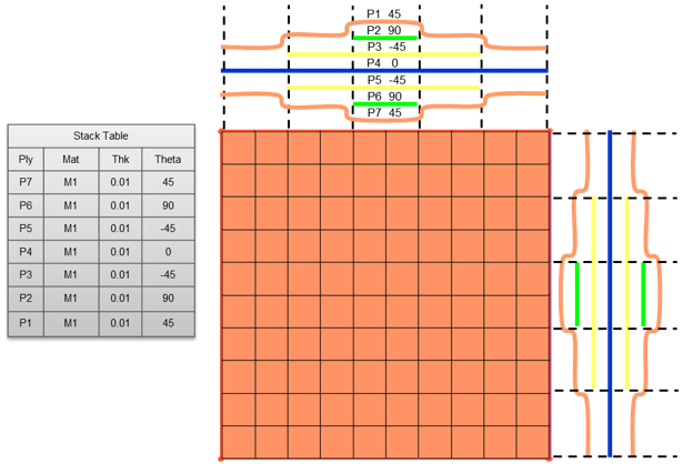
Ply-based modeling.
Ply-based modeling provides an FEA methodology which is consistent with the composite manufacturing process. The ply-based modeling entities replace, and can generate, typical solver zone-based composite properties.
- Laminate(s)
- Typically, one laminate per physical part is defined. Primarily, laminates contain the stack of plies. Additionally, laminates specify symmetry and repeats of plies within a laminate, along with information that can manipulate the ABD matrices.
- Plies
- Plies define the material, thickness, orientation (from reference on element/property material direction) and shape (Elements, or element sets if FEA-based. Lines, surfaces or solids if geometry-based).
- Template Property
- If user profile is OptiStruct, a PCOMPP is used. If another user profile is selected, a standard zone-based composite shell property is used. The property defines typical solver specific attributes like offset and non-structural mass. Layer information does not need to be entered. It is automatically populated from the defined plies and laminate.

Figure 2.
Ply-based models can optionally be used to generate zone-based shell models, continuum shell, and solid models.
Zone-Based Shell Modeling
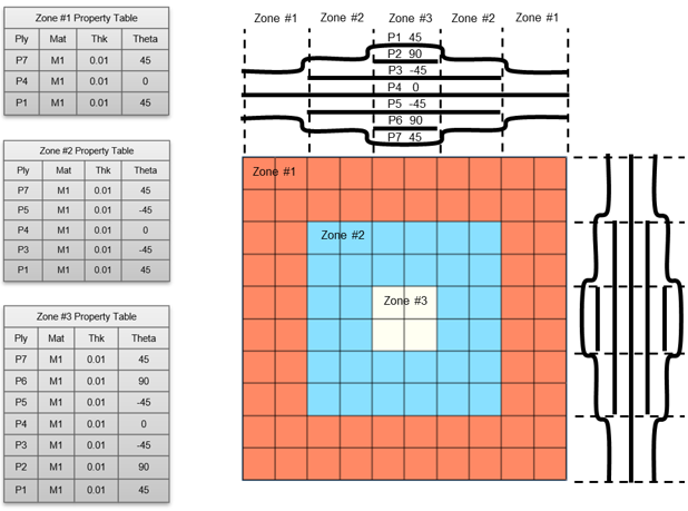
Zone-based modeling.

Figure 3.