Visualization
Set element mark options and general visualization options.
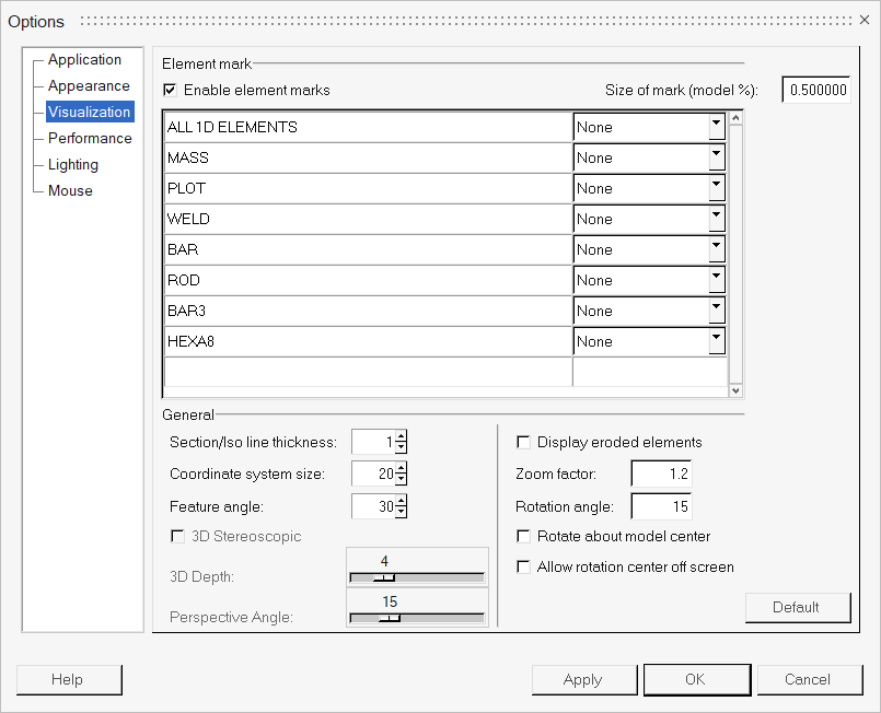
Figure 1. Visualization Options
| Enable element marks | Displays element types with the corresponding shapes selected from the drop-down menu. |
| Size of mark (model %) | Specifies the mark size as a percent of a model size. |
| ALL 1D
ELEMENTS MASS PLOT WELD BAR ROD BAR3 HEXA8 |
Each element type listed can be displayed as a dot, cube, sphere, or cylinder. |
Additional options can also be set in this dialog:
| Section/Iso line thickness | Specifies the section or iso-line thickness. The value can range from 1 to 6. | |
| Coordinate system size | Specifies the size of the coordinate system. The default is 20. | |
| Feature angle | A feature angle is used to calculate feature lines
of an FEA model. The specified value is used as the threshold for selecting entities By Face (in the Extended Entity Selection Menu). |
|
| Display eroded elements | Displays elements that are eroded/failed or deleted during explicit solver calculation, such as LS-DYNA and Radioss. By default, HyperView hides the deleted elements so the failed elements are not displayed during animation. | |
| Zoom factor | Specifies the multiplication factor that is used to increase or decrease the scale of the current view. The default is 2. | |
| Rotation Angle | Specifies the increment (in degrees) that will be used when rotating a model using the view controls toolbar. The default is 15. | |
| Rotate about model center | Allows you to change the rotation behavior in the
modeling window, if any specific rotation center is
defined. When this option is active the model rotates around the center of all
current visible entities, whereas the model rotates around the center of the
screen when the option is inactive. Note: The different behaviors can only be seen
when the model is not positioned in the center of the screen.
|
|
| Allow rotation center off screen | Activate this check box to maintain the same rotation center even when it moves off the screen. | |
| 3D Stereoscopic | Activating this check box automatically enables the
Perspective view mode and provides you with 3D viewing capabilities in HyperView. The model will be displayed in the 3D mode during
view manipulation until this option is deactivated. The Perspective option in the Display Control drop-down menu is disabled when the 3D Stereoscopic option is activated to show that the 3D specific Perspective Angle (see below) is being used instead of the per window perspective. See the 3D Stereoscopic View topic for additional details regarding setting up the 3D Stereoscopic feature. Depending on the hardware and model that you are using, the performance may be affected by the 3D display (which could potentially be up to half of the 2D frame rate). |
|
| You can use the options listed below to customize the depth and angle of the model while in 3D view mode. These 3D specific options are per session options. | ||
| 3D Depth | Use the slider bar to adjust the amount that the objects appear to come out of the screen. | |
| Perspective Angle | Use the slider bar to control the perspective angle while the 3D option is enabled. | |
| The 3D adjustment slider and perspective options are disabled when the 3D option is deactivated. | ||