Appearance
Set display options such as background color, foreground color, and mesh lines.
Click Appearance on the tree to view the various options.
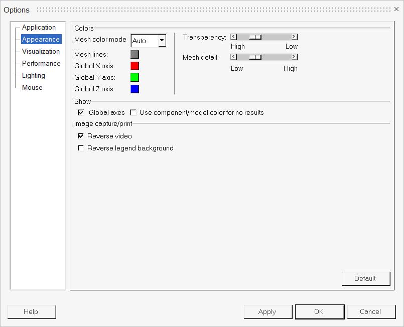
Figure 1. Appearance Options
| Colors | Allows you to change the color of one of the following features: | |
| Mesh color mode | The mesh color mode is set to Auto, which uses the component color as the basis of the mesh line color. This option can be changed to a custom mesh line color using the Override option, which will use the selected custom mesh line color for the entire mesh. | |
| Mesh lines | Changes the mesh line color. Click on a color box, select a new color from the palette, and click OK. | |
| Global X/Y/Z Axis | Changes the colors of the global X, Y, and Z axes. | |
| Show | ||
| Global axes | The global axes can be displayed in the lower left corner of the HyperView window. Click the Global axes check box to toggle the display of the axes on or off. | |
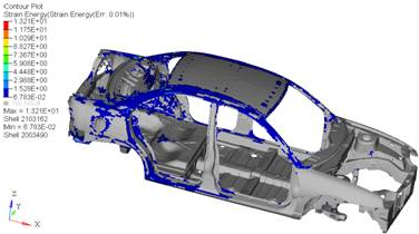
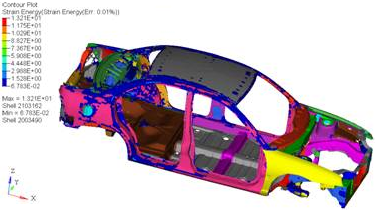
| Use component/model color for no results | Retains the component or model colors when no results exist. This option is
turned off by default. An example for components is shown below:
Having this option checked may reduce the graphics performance while animating, rotating, or panning the model. A frame rate reduction is noticed with the option turned on. |
|
| Image capture/print | ||
| Reverse video | Reverses the background color to white and the text to black. This provides better quality for printing and image capturing. | |
| Reverse legend background | Reverses the background color of a non-transparent legend to white and the text to black for image capture and printing. | |
| Transparency | Allows you to set and change the level of transparency for entities that are displayed with transparent attributes. Use the slider bar to set the Transparency level from High to Low. | |
| Mesh detail | Allows you to set and change the level of detail
used when displaying mesh lines. This new implementation of displaying mesh lines
uses an algorithmic technique based on many factors including: model size, zoom
factor, mesh coarseness, and component color. The default option is set using generalized settings that work well on most models. However this can be changed using the Mesh detail slider (ranging from 1 to 100), which will keep the mesh lines displayed at further zoomed out levels regardless of mesh coarseness by moving the slider toward the "High" setting. The Mesh color mode is set to Auto, which uses the component color as the basis of the mesh line color. This option can be changed to a custom mesh line color using the Override option, which will use the custom chosen mesh line color for the entire mesh. This new mesh line implementation has some limitations in version
14.0 that when triggered will revert back to the older legacy mode of displaying
mesh lines, which is similar to HyperView 13.0’s regular black mesh lines. The
limitations are:
Note: Feature and Edge lines display modes have not changed in appearance
in version 14.0.
|
|