Topology View
Topology View displays an entity, system or a model in a schematic form to study the topological connectivity it has with other entities within or outside of its parent system.
Topology View is available on the following entities: Bodies, Joints, Bushings, SpringDampers, Forces and Beams, System, Assembly and Analysis.
Opening the Viewer
- Select an entity in the Project Browser.
- Right-click and select Topology View.
The Topology View browser tab opens on the right side of the application.
The topological connections can be viewed at a system/assembly level or at the level of the entire model.
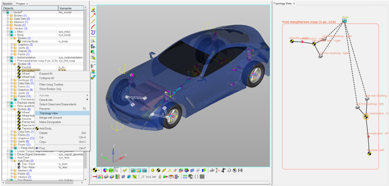
Figure 1.
Features
- Entity selected in the Topology View Browser is highlighted in the graphics area and entity panel appears.
- The topological tree can further be expanded by double clicking on entities.
- The entity node can be repositioned by dragging it.
- Systems can be expanded/collapsed using double left click/right click.
- Changing the selection in the Project Browser updates the view in the Topology View Browser.
Limitations
Topology View is best suited to visualize a finite set of entities and its connections. The tool may not be suited for schematic visualization of very large systems/model.