Pretension Manager
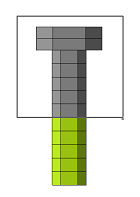
Use the Pretension Manager tool to create and edit 1D and 3D pretension bolt loads and bolt sections for the OptiStruct solver.
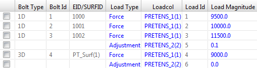
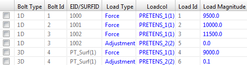
Pretension Manager Dialog
| Column | Description | Related OptiStruct Card(s) |
|---|---|---|
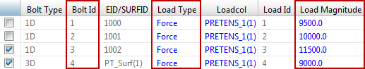
| Bolt Type | Displays the type of bolt the load is applied to. Can be 1D or 3D. | PRETENS |
| Bolt Id | Displays the identification number of the Bolt Pretension section the load is applied to. | PRETENS |
| EID/SURFID | Displays the Element (1D) or Surface (3D) identification number where the Bolt Pretension section is located. | PTFORCE, PTADJST |
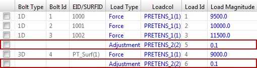
| Load Type | Allows you to review and edit the type of pretension load, by
selecting one of the following options from the pull-down
menu:
Use the Control key to select and edit this field in multiple rows at once. Click OK or Apply to update the load types in the model. Click Cancel to exit the Pretension Manager without saving any changes. |
PTFORCE, PTADJST |
Allows you to review and edit the Load Collector where the
pretension load is organized in HyperMesh, by
selecting one of the following options from the pull-down
menu:
Use the Control key to select and edit this field in multiple rows at once. Click OK or Apply to update the load types in the model. Click Cancel to exit the Pretension Manager without saving any changes. |
PTFORCE, PTADJST | |
| Load Id | Displays the HyperMesh internal identification number of the individual loads. | |
| Load Magnitude | Allows you to review and edit the pretension load
magnitude. Use the Control key to select and edit this field in multiple rows at once. Enter a new value and press Enter to apply the changes to all of the selected rows. Click OK or Apply to update the load types in the model. Click Cancel to exit the Pretension Manager without saving any changes. |
PTFORCE, PTADJST |
| Orientation | (Optional) Allows you to review and edit the determination
type of the normal direction of the bolt pretension section, by
selecting one of the following options from the pull-down
menu:
|
|
| Output DOF ID | (Optional) Allows you to review and edit the SPOINT that
contains the pretension deformation and load, by selecting one
of the following options from the pull-down menu:
Use the Control key to select and edit this field in multiple rows at once. The Output DOF ID value will be updated in the model immediately after editing selection. |
PRETENS |
| Button | Description |
|---|---|
| Add 1D Bolts | Allows you to create one or more 1D Bolt Pretension
sections. To add a 1D Bolt Pretension section:
|
| Add 3D Bolts | Allows you to create one or more 3D Bolt Pretension Sections.
Two options are available when you click Add 3D
Bolts:
When you are using the Create New Surface option, a default name will be automatically assigned in the panel using the prefix PRETENS_* and the appropriate card image. Once you click Create and Return, you will be brought back to the Pretension Manager. The Pretension Manager will now display a 3D Bolt Pretension section for the new contact surface. |
| Add Load | Allows you to add a new pretension load to an existing Bolt
Pretension section. To add a new pretension load to an
existing
Bolt Pretension section:
|
| Delete | Deletes the selected bolt pretension sections and/or
pretension loads. To delete selected bolt pretensions
section:
When a Bolt Pretension section has more than one load applied to it, deleting the bolt section at the top level will automatically delete all the loads applied to it. On the other hand, deleting single additional loads will only remove the selected loads. |
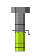
| Review | Allows you to graphically review the Element/Surface, Load,
and SPOINT assigned to the selected Bolt Pretension section.
This button also displays more detailed information about the
selected Bolt Pretension section's Orientation. To review a
Bolt Pretension selection:
|
| Select All | Select all rows in the table. |
| Select None | Deselect all rows in the table. |
| Select Reverse | Reverses row selection in the table. |
| View | Controls the Pretension Manager table's
view organization mode. There are two options available from the
pull-down menu:
|