Preferences
Configure the view and behavior of HyperMesh.
Color Settings
Color settings control the display color of the user interface, as well as the display color of geometry and mesh entities.
From the menu bar, click .
General
- Background 1/Background 2
- Select any colors for Background 1 and Background 2, which control the color of the
background gradient in the graphics area.
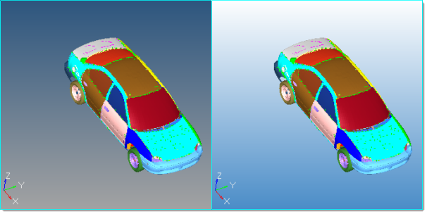
Figure 1. - Gradient Direction
- Select one of the gradient boxes to change the direction and style of the gradient in the graphics area. The boxes themselves illustrate the gradient pattern that they apply, but not the current colors.
- Show Global Axes
- Show the global axes in the graphics area.
- Global X axis / Global Y axis / Global Z axis / Axis label
- Change the colors of the X, Y, and Z global axis vectors. By default, the X axis is red, the y axis is green, and the Z axis is blue.
- Change the color of the axis labels. By default, the axis labels are white.
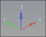
Figure 2. - Text and Line Color
- Change the color of all the text and lines that displays in the graphics area to be black. By default, the text is white.
Geometry
Access color settings that control the geometric entities in the Geometry tab.
- Surface data
- Free edges
- Edges of surfaces that do not connect to any other surfaces.
- Shared edges
- Edges of surfaces that connect to one other surface.
- Suppressed edges
- Shared edges that have been manually suppressed so that the automesher treats the shared surfaces as if they were one surface, allowing elements to cross the edge as if it were not there at all.
- T-junctions
- Edges shared by 3 or more surfaces.
- 3D Solids
- Fin faces
- Surfaces that split a 3D solid entity, but only partway through. They do not actually extend through the entire entity.
- Bounding faces
- The outer faces of solid entities.
- Full partition faces
- The faces of adjoined solids.
- 2D faces (topo)
- When using the by 2D topo visualization mode, this is the color of 2D faces that are not part of a solid.
- Ignored (topo)
- The color of 2D faces when using the by 2D topo visualization mode.
- Edges (comp)
- Mesh edges when coloring mesh with the by comp visualization mode.
- 1 dir. map
- Visualization for solids that can be mapped (for 3D meshing) in one direction.
- 3 dir. map
- Visualization for solids that can be mapped (for 3D meshing) in three directions.
- Not mappable
- Visualization for solids that have been edited, but still require further partitioning to create mappable solids.
- Ignored map
- Default visualization for solids that require partitioning to become mappable.
Mesh
- Mesh line
- Specify the color of the lines on a mesh that indicate the edges of mesh elements. By default, mesh line is set to auto, which assigns the component color as the mesh line color. To select a custom mesh line color for the entire mesh, click the toggle.
- Elems, no prop/mat
- Specify the color for elements that do not currently have any properties or materials assigned to them, either directly or inherited from the collectors that they belong to.
Mesh/Geometry Appearance Settings
Mesh/Geometry Appearance settings control the display of mesh lines, geometry lines and application level anti-aliasing.
From the menu bar, click .
Meshing
- Detail: Mesh Line Settings
- Moving the Detail slider from 1 to 10 allows the displaying of mesh lines when you are viewing the model at further zoomed out levels regardless of the mesh coarseness.
- Transparency: Finite Element Settings
- Moving the Transparency slider from 2.0 to 9.5 adjusts the transparency levels of finite element models from more opaque to more transparent.
- Transparent with mesh lines
- Check this box on to display mesh lines when finite elements are transparent.
Geometry
- Detail: Geometry Line Settings
- Moving the Detail slider from 1 to 10 allows the displaying of geometry lines when you are viewing the model at further zoomed out levels.
- Solid edge width: Geometry Solid Edge Line Width Setting
- Moving the Solid edge width slider from 1.0 to 5.0 allows the displaying of geometry solid edge line width thickness.
- Auto edge adjustment
- Check this box on to change the geometry line widths dynamically when zooming in and out.
Other
- Anti-aliasing
- Check this box to remove jagged edges and smooth all graphic lines.
- Show newly created entities
- Check this box to display entities as they are created.
- Transparent Highlight
- Check this box to display new selection highlights with a transparency effect. Outer edges appear white and thicker.
- Node level of detail
- Node size will vary on zoom in or out of the model in the graphics area, and no longer shows overlapping of nodes.
Lighting Settings
Lighting settings control the location, direction and intensity (high/low) of the specular lighting.
- One light
- Manually control the direction of lighting, and adjust the specular lighting by
moving the slider.
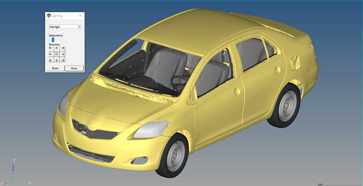
Figure 3. - Multi-lights (default)
- Use the standard placement of the multiple lights, and adjust the specular lighting by moving the slider.
- This setting does not allow for directional control.
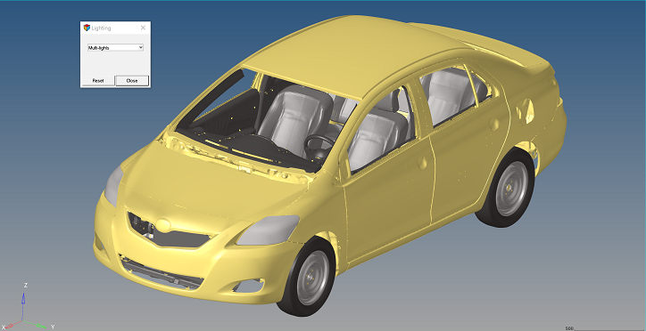
Figure 4.
Scale Settings
Scale settings control the scale display in the graphics area.
- Scale Position
- Select a location to display the scale.
- Scale Size
- Select a display size for the scale.
- Scale Color
- Pick a color to display the scale.
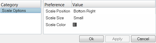
Figure 5.
Script Performance Settings
Script Performance settings control the APIs used to improve script performance when the original script may not have cleaned itself up correctly due to poor logic, unhandled errors or unexpected behavior.
From the menu bar, click .
If you experience issues with entity selection not highlighting, messages not posting to the status bar, command files not populating or graphics not redrawing, reset the settings in this dialog.
Manage Favorite Panels
Save and access a list of your favorite panels. HyperMesh saves the list of favorite panels and restores it accordingly when you start a new session.
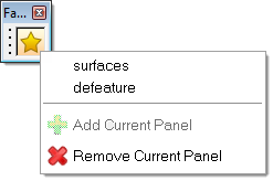
Figure 6.
Add Favorites
- Open the panel you wish to save to the favorite panels menu.
-
From the Favorites toolbar, click
 and select
Add Current Panel.
and select
Add Current Panel.
Remove Favorites
- Open the panel you wish to remove from the favorite panels menu.
-
From the Favorites toolbar, click and select
Remove Current Panel.
Change Solver Interfaces
Load a different solver interface in HyperMesh.
-
From the Standard toolbar, click
 .
.
- In the User Profiles dialog, select a solver interface and click OK.