Create Tetra Mesh with the Tetramesh Process Manager
Navigate through the different steps necessary to create a high quality tetramesh quickly using the Process Manager.
Effective tetrameshing requires a standard surface mesh to use as a base from which the 3D tetras are built, therefore the beginning steps of the process revolve around achieving quality surface meshes.
Specific geometry cleanup and meshing algorithms are implemented in the Tetramesh Process Manager template to handle complex parts efficiently.
A specific tetramesh process instance can be saved in a process manager template file (*.pmi) so its parameters can be reused later on similar parts, allowing for increased efficiency and implementation standards. The Tetramesh Process template can be used for automated geometry and element cleanup (BatchMesher).
Create New Session
You can go back and forth between template panels and core panels to take
advantage of core functionality by undocking the The Process Manager browser and panel open. panel. To dock and
undock the The Process Manager browser and panel open.
panel, click ![]() .
.
Import Geometry
-
Select geometry.
To import Do this Geometry - For Import Type, select Geometry.
- For File Type, select the type of geometry to import.
- In the Import Filename field, navigate to the desired file.
- To automatically save an imported CAD file as an HyperMesh file after the import completes, select the Save HM File After Import checkbox.
- In the Scale Factor field, enter a scale factor if the imported
model is in a spatial scale other than what you want to work
with.This feature can also be used to convert the model's measurements between metric and English units, for example.Note: Only spatial units are affected, mass and similar qualities are not.
- For Cleanup tol, choose a method to perform cleanup on imported
geometry.
- Choose Automatic to use the global cleanup tolerance specified on the Options panel, Geometry subpanel.
- Choose Manual to enter your own tolerance.
- To move all entities marked as blank to a special component, select the Import blanked (no show) components checkbox. By default, the translator ignores all of the blank flags in the file.
HyperModel Model - For Import Type, select HM Model.
- In the Import Filename field, navigate to the desired file.
- Click Import.
- Click Next.
Cleanup Geometry
-
Cleanup geometry.
To cleanup geometry by Do this Equivalencing free edges - Click the Free Edges tab.
- In the Tolerance field, enter the maximum distance across which
surfaces can be made equivalent.
Surfaces with a gap between them greater than this value will not be made equivalent.
- Click Equivalence.
Displaying free edges by edge type - Click the Edge Tools tab.
- Select the checkboxes (Free Edges / T-junctions) for the edge types to display.
- Adjust display.
- Click Isolate to display only the surfaces attached to the selected edge types.
- Click Display All to remove the mask and view all surfaces.
Create filler surfaces - Click the Edge Tools tab.
- Click Create to generate filler surfaces for all the free edge loops.
- Click either Accept or Next to continue.
Organize and Cleanup Holes
Isolate holes based on diameter ranges. Isolating and meshing holes separately from other geometry features is a very important step during tetra meshing; failing to do so can drastically affect the overall mesh quality. You may also wish to use this step even when there are no specific meshing requirements for holes just to organize your model.
-
Click Auto Organize to automatically organize the holes
into separate components based on the input parameters, diameter, and so
on.
One component will be created for each row in the table, and the holes are placed into the components that their diameter and other criteria match. The model holes, and corresponding table rows, are color-coded according to the component that they have been sorted into.
Clicking one of these buttons selects the entire row, making it the "active" row. To deselect an active row, click the colorless button at the very top-left corner of the table (the one in the header row along with the column names).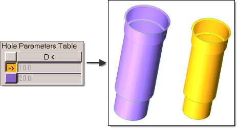
Figure 1.
Mesh Holes
-
From the Mesh Type column, select the mesh type to use when meshing the
holes.
There are two meshing options available: R-tria regular and R-tria union jack.

Figure 2. R-tria regular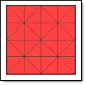
Figure 3. R-tria union jack -
Mesh holes.
Each row has a color button on its left which corresponds to the component holding hole surfaces. Clicking one of these buttons selects the entire row, making it the "active" row. To deselect an active row, click the colorless button at the very top-left corner of the table (the one in the header row along with the column names).
- To mesh a single group of hole, select it's corresponding row and click Mesh.
- To mesh all of the holes simultaneously, click Mesh All.
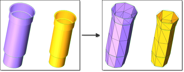
Figure 4.
Organize and Cleanup Features
Organize and cleanup user defined features such as water jackets, inlets, outlets and contact surfaces.
Auto cleanup operations are based on the criteria set in the BatchMesher criteria file. Cleanup operations include equivalencing free edges, fixing of small surfaces (relative to the element size), and detection of features such as beads. It also performs specified surface editing/defeaturing operations like removal of pinholes below a specified size, removal of edge fillets, and the addition of a layer of washer elements around holes.
The Autocleanup panel performs the entire geometry cleanup portion of the BatchMesher. Since it performs a variety of geometry cleanup tasks, the results will not be instantaneous and can take a few minutes for large models. Cleanup criteria is determined by the BatchMesher parameter and element quality criteria files, both of which can be edited from within this panel using the BatchMesher Parameter Editor.
Organize and Cleanup Fillets
Defeature fillets, and replace the rounded corner where two lines come together with a point. Tangents are calculated at the beginning and at the end of each fillet, then those tangents are intersected to create a corner.
Before you begin, make sure the Process Manager, Fillets and Organize panel is open.
-
To suppress such edges after the fillet removal process, select the
Suppress fillet tangent edges checkbox.
Because fillets are removed by generating tangent lines to replace them, these lines often result in extra edges in model geometry.
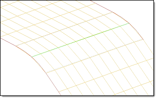
Figure 5. Suppress Fillet Tangent Edges On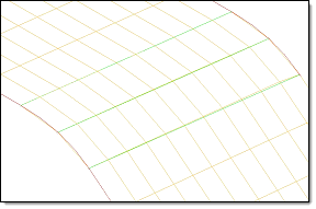
Figure 6. Suppress Fillet Tangent Edges Off
Mesh Features
Before you begin, make sure the Process Manager, Mesh Features panel is open.
- For Mesh Type, select the type of elements used to generate the mesh for each feature.
- In the Elem Size field, enter the element size used to generate the mesh for each feature.
-
Create mesh.
- To create mesh for the selected/active row, click Mesh.
- To create mesh for all rows, click Mesh All.
- Click either Accept or Next to continue.
Delete the mesh from a specific component by selecting the desired row and clicking Delete Mesh.
Organize and Cleanup Global Surfaces
Organize and clean up all remaining global surfaces, that is, surfaces that were not already covered by holes and user-defined features.
Before you begin, make sure the Process Manager, Global Organize and Cleanup panel is open.
Mesh/Remesh Global Surfaces
Mesh all remaining global surfaces, that is, surfaces that were not already covered by holes and user-defined features.
Before you begin, make sure the Process Manager, Mesh/Remesh panel is open.
Cleanup Elements
Optimize the quality of the elements created during each of the previous meshing stages.
Before you begin, make sure the Process Manager, Element Cleanup panel is open.
-
Perform automatic cleanup.
Note:
The nodes of features, such as ridges, will not be preserved if their angle is less than the specified minimum angle. In addition, element quality requirements may override feature angle preservation regardless of the angle specified.
-
In the Max Feature Angle field, enter the maximum feature angle to
preserve.
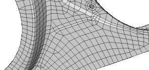
Figure 7. Minimum Feature Angle (Low Value)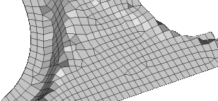
Figure 8. Minimum Feature Angle (High Value)
The mesh is examined within each component individually, removing elements of poor quality and stitching the mesh together to fill the resulting gaps. Cleaning up the mesh on a per-component basis prevents mesh overlap between adjacent surfaces that belong to different components.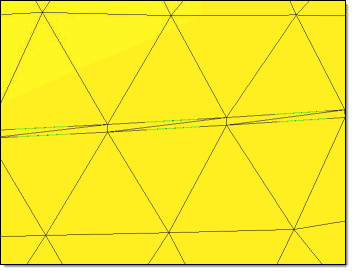
Figure 9. Before Element Cleanup. Notice the "sliver" elements along midline.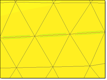
Figure 10. After Element Cleanup. Notice the small, sliver elements are removed. -
In the Max Feature Angle field, enter the maximum feature angle to
preserve.
Perform Tetra Meshing
Generate the 3D mesh from the existing surface meshes.
Before you begin, make sure the Process Manager, Tetra Meshing panel is open.