Acoustic Cavity Meshing
Acoustic Cavity meshing generates a fluid volume mesh used to calculate the acoustic modes (or standing waves) inside the air spaces of a vehicle or similarly enclosed structural model.
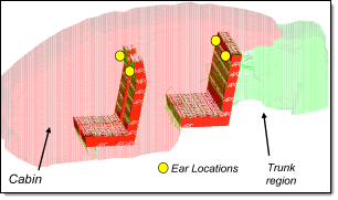
Figure 1.
Acoustic cavity meshing can be a CPU-intensive process, especially with fine and/or complex meshes, but this can be offset by additional CPU cores. The Acoustic Cavity Mesher is multithreaded to take advantage of multi-core environments.
How Cavities are Identified
Hole and gap patching is a critical part of defining cavities enclosed in the structure model. The process refers to patching over inconsequential gaps and holes that inevitably exist in the structure model, such as speaker holes.
Gaps are defined as elongated openings based on their longest dimensions. Holes are openings defined by the radius of a sphere that can pass through them. By specifying the size of the hole and gap patches, you can control how the cavities are defined through auto search.
Typically, a cavity model is intended to be meshed right up to the outer body panel. Plastic and fiber trim panels are often included in a trimmed body model, but not meant to be used for cavity meshing. However, if the trim panels are selected during the AC meshing process they can be confused as outer body panels, leading to incorrect cavity definition. Therefore, it is important to ensure that only the exterior body panels are selected as the structure components to be included in the auto cavity search.
- Door
- Include the cavity between the inner and outer door panels as a part of the interior by specifying a hole patch size smaller than that of the largest opening in the inner panel, so that the opening is not patched. This allows interior mesh to flow into the door cavity.
- Instrument Panel (IP)
- Model the cavity behind the Instrument Panel as a part of the interior cavity by excluding the IP parts from the structure component selection during the auto cavity search. This forces the auto cavity search to ignore the existence of the sealed IP cluster when determining the interior volume of the passenger compartment. If the IP panel needs to be treated as a radiating source, a fluid boundary needs to be created at the location of the IP, similar to the how a package tray can be included as a structure part.
- Pillar
- Include large pillar cavities, such as a D pillar cavity, as a part of the interior cavity by ensuring that the gap and hole patch size specified are smaller than that of the largest opening. This prevents the opening from being patched and allows interior mesh to flow into the pillar cavity.
- Under Seat
- Ensure the under-seat spaces are meshed by specifying an element size smaller than the smallest dimension of the space, thus allowing the interior mesh to fill the cavity.
- Trim Component
- Special functionalities are required to mesh these cavities.
Factors that Influence Cavity Meshing
The ability to model the acoustic cavity and predict acoustic response inside it is a critical part of NVH analysis, as noise level and quality become key product quality differentiators in the marketplace. A number of factors need to be considered when meshing an acoustic cavity model.
- Adequate mesh size.
- A rule of thumb is that at least six elements are needed per acoustic
wavelength. Based on this rule, the minimum acoustic element sizes at
various frequencies are:
- 500 Hz
- 114 mm
- 1000 Hz
- 57 mm
- Mesh quality as defined by Jacobian value, Tetra Collapse, and similar measures.
- Poor mesh quality may cause problems when submitted to the solver, or lead to less-accurate results.
- How closely the cavity shape matches the actual structure.
- This impacts how accurately the cavity model captures acoustic modes, and how difficult it is to obtain good coupling between the fluid and structure. It is important to define the structure panels intended to be coupled to the cavity.
- Aesthetics of the cavity mesh.
- The model may appear too jagged if the cavity mesh matches the structure closely. Some users prefer a smooth looking mesh for presentation purposes, but care must be taken so that this does not adversely affect the modes calculated or the quality of coupling generated when default ACMODL search parameters are used.
- Interior response definition.
- Interior response points need to be defined so that they become a part of the mesh definition when cavity mesh is generated.
- Seat Foam Cavity definition and coupling.
- Seat foams are typically modeled as denser air cavities. Their geometry definition can come in either as CAD data or existing FE mesh. Some seat models contain detailed foam curvature definition, while others may just be blocky boxes. The acoustic mesher can generate a new seat foam mesh and use congruent grids to connect to the interior cavity elements, or generate fluid MPCs to connect grids on a existing foam cavity mesh to the interior cavity mesh.
- Trunk Cavity separated from the Interior Cavity.
- For passenger sedans, the trunk cavity is typically modeled as a separate cavity from the interior, separated by the rear seat back foam cavity.
- Package Tray properly coupled to both interior and trunk cavities.
- For passenger sedans, the "package tray" or "parcel shelf" is situated behind the rear seat backs, between the interior cavity on the top and the trunk cavity below. Its vibration should be coupled into both cavities. This means a boundary (or gap) needs to exist in the cavity model where the package tray is located. This is typically accomplished by the two cavities not sharing grids at the boundary.
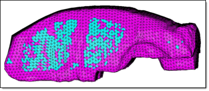
Figure 2.
Create an Acoustic Cavity Mesh
Creating an acoustic cavity mesh is two-staged. First, create a voxel-based preview mesh. Second, select individual volumes, set element quality requirements, and create a smoother, more refined computational mesh for the selected volumes.
Acoustic Cavity meshing begins with the Acoustic Cavity Mesh panel. This panel accepts the necessary base input data to generate a voxelated preview mesh for one or more acoustic cavities. Once the preview mesh exists, however, the Acoustic Cavity Browser displays in the tab area; you can use this tool to modify element quality checks, select specific volumes that have a preview mesh, and create the computational mesh for each selected cavity.
-
Define acoustic cavity meshing parameters.
-
In the Acoustic Cavity Browser, click
 .
.
- In the Options dialog, define acoustic cavity meshing parameters accordingly.
-
In the Acoustic Cavity Browser, click
-
Using the Acoustic Cavity Mesh panel, generate preview mesh.
A simple preview mesh is generated.
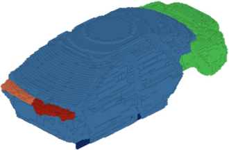
Figure 3. Simple Preview Mesh -
In the Acoustic Cavity Browser, select individual volumes, set element quality
requirements, and create a smoother, more refined computational mesh for the
selected volumes.
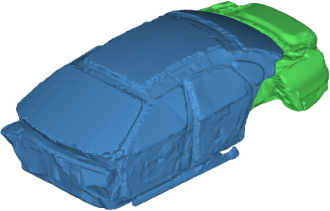
Figure 4. Final Acoustic Cavity Mesh