Mesh Modes
Mesh modes are used during automatic meshing to determine the type of meshing to perform.
Size and Bias
Uses elements of a uniform size that you specify to create mesh. When using existing finite elements as the basis for mesh generation, feature recognition settings allow the mesher to break up the areas defined by the selected elements into logical groupings with mesh controls set for each group boundary.
QI Optimize
An iterative automatic mesh generation method driven by element quality criteria. During the mesh generation process, the quality index of the mesh is determined by evaluating each element against a set of element quality tests. If all required element quality criteria are passed, then that element has a perfect quality index of zero. As the element quality deteriorates, the quality index value increases; so a lower quality index score indicates an element more closely meets the ideal quality requirements.
The compound quality index is the sum of the quality index values for each of the elements that are included in the current meshing area. The quality index value itself has no direct physical meaning; it is a way to compare one generated mesh pattern against another pattern generated for that same area. The quality index based mesh optimization routine attempts to modify the mesh pattern and apply node smoothing routines to obtain a lower overall quality index value.
Edge Deviation
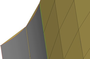
Figure 1. . When meshing curved surfaces, the planar elements (tan color) can deviate from the curved grey geometry.
Edge deviation applies to both surface geometry and when re-meshing elements. Automeshing with edge deviation automatically selects the best element size to approximate a curve, within the limits that you specify. The maximum deviation and maximum feature angle parameters are the primary controls for this effect.
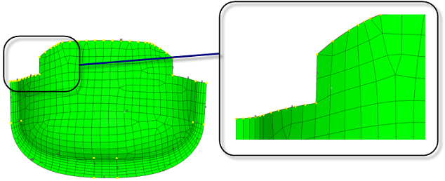
Figure 2. . Edge deviation control when meshing creates smaller elements and spaces nodes closer together to limit how much the elements can deviate from the surface edges.
Surface Deviation
Creates mesh within the limits of element deviation from a surface.
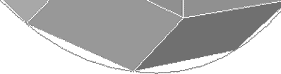
Figure 3. . A gap is visible between the curved edge of the surface and the element edges.
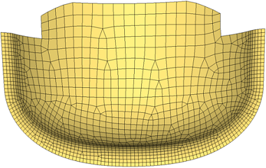
Figure 4. . With surface deviation meshing, smaller elements are used to accurately represent curved surfaces. Larger elements are used where the geometry shows less curvature.
Rigid Body Mesh
Creates mesh to represent the topology of a rigid object.
Rigid bodies are surfaces that are expected to be treated as undeformable in the solution. One example of a rigid body is in metal-forming. When modeling the results of a die pressing down on a metal sheet, it is important to model the shape of the die because that determines the shape of the metal sheet after being pressed. However, during a forming analysis the stresses and deformations of the die itself are not of interest, only those of the formed metal sheet. Other applications for rigid bodies include the impactors used in vehicle crash simulation.
A mesh that accurately represents the rigid geometry is important for such simulations to allow the solver collision detection routines to work effectively and accurately. Since stress and deformation of the rigid body are not calculated by the solver, the rigid body mesh focuses on accurately modeling the shape of the body rather than on producing a high-quality mesh. To this end, Rigid Body meshing uses the same faceting and shading routines that are used for drawing the model graphics. The resulting mesh may have high aspect ratio or extremely tapered elements that would not be suitable for solution, but can accurately represent the geometry.

Figure 5. . When creating a surface deviation based mesh on this cone, many small elements are required to capture the geometry, even so, the elements exhibit a lot of warpage and those at the tip are distorted and do not accurately represent the geometry.

Figure 6. . With the rigid body mesh, the shape of the object can be accurately modeled using fewer larger elements since the element shape is not a concern.