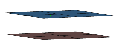
Creates hexa element with DCOUP3D elements projecting and connecting to the
surrounding shell elements. This realization uses the shell thickness to calculate the
hexa offset from the shell elements. In the case where the model is a 3T connection, the
acm (equivalenced-(T1+T2)/2) realization will join the hexa elements.
This realization uses the prop_abaqus_acm.tcl4 property script. Figure 2.
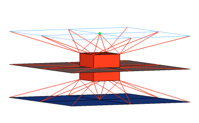
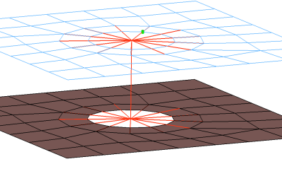
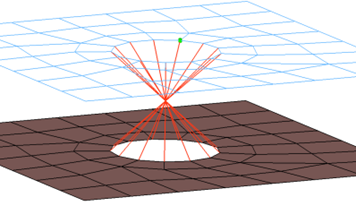
Creates DCOUP3D elements for the head and element for the body. The head elements
project and connect to the nodes of the adjoining shell elements. Figure 3.
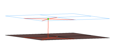
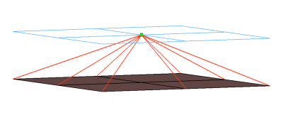
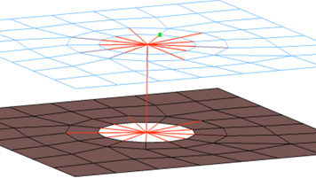
Creates KINCOUP elements for the head and element for the body. The head elements
project and connect to the nodes of the adjoining shell elements. Figure 4.
CFG abaqus 6 bush
*filter spot
*head
rigidlink 1 1
*body 0
rod 13 1
Abaqus bolt (b31)
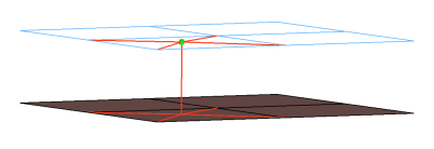
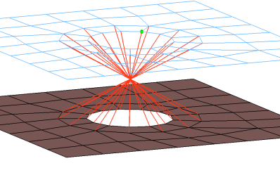
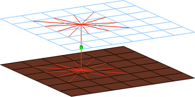
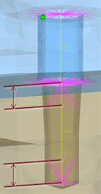
Creates KINCOUP elements for the head and B31 element for the body. The head elements
project and connect to the nodes of the adjoining shell elements that form the hole, and
also to the second row of nodes to form the washer layer. The connector location can be
on the edge of the hole, center of the hole, midpoint in between the two, holes or on
the second row of nodes which form the washer layer.
This connector also uses the script prop_abaqus_b31.tcl3. Figure 5.
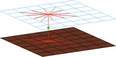
Creates KINCOUP elements for the head and B31 element for the body. The rot x degree
of freedom is constrained. The head elements project and connect to the nodes of the
adjoining shell elements that form the hole, and also to the second row of nodes to form
the washer layer. The connector location can be on the edge of the hole, center of the
hole, midpoint in between the two holes, or on the second row of nodes which form the
washer layer.
This connector also uses the script prop_abaqus_b31.tcl3. Figure 6.
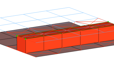
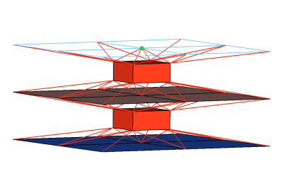
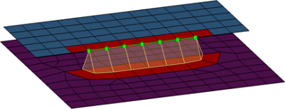
Creates a row of hexa/penta elements for the body and numerous DCOUP3D/KINCOUP
elements for the head. The head elements project and connect to the nodes of the
adjoining shell elements. If there is a direct normal projection then a KINCOUP element
will be used, if there are only non-normal projections then DCOUP3D elements will be
created. The size (thickness) for the hexa and/or penta elements depends on the chosen
option: shell gap, (T1+T2)/2, mid thickness, const. thickness, maintain gap.
Note: The
exact hexa position is also influenced by the option consider shell thickness and
offset for hexa positioning. See hexa positioning for hexa adhesives and ACMs for
details.
This realization uses the prop_abaqus_acm.tcl4 property script. Figure 7.
Creates a KINCOUP element. The element projects and connects to the nodes of the
adjoining shell elements that form the hole, and also the nodes that form the washer
layer. The connector location can either be on the edge of the hole, center of the hole,
midpoint in between the two holes, or on the second row of nodes which form the washer
layer. Figure 9.
Creates KINCOUP elements for the head and B31 element for the body. The head elements
project and connect to the nodes of the adjoining elements, forming the hole and also
the second row of nodes which form the washer layer. The connector location can either
be on the edge of the hole, center of the hole, midpoint in between the two holes, or on
the second row of nodes which form the washer layer. Figure 10.
Creates a KINCOUP element, which projects and connect to the nodes of the adjoining
elements which form the hole. The connector location can either be on the edge of the
hole, center of the hole, midpoint in between the two holes, or on the second row of
nodes which form the washer layer. Figure 11.
Creates KINCOUP elements for the head and the body. There are two individual KINCOUP
elements at the head of the connection, one to connect to the inner row of nodes, and a
second to connect to the washer layer nodes. The connector location can either be on the
edge of the hole, center of the hole, midpoint in between the two holes, or on the
second row of nodes which form the washer layer. Figure 12.
Creates KINCOUP elements for the head and the body. There are two individual KINCOUP
elements at the head of the connection, one to connect to the inner row of nodes, and a
second to connect to the washer layer nodes. The KINCOUP head element that connects to
the washer layer nodes only connects to every other node on the washer layer. The
connector location can either be on the edge of the hole, center of the hole, midpoint
in between the two holes, or on the second row of nodes which form the washer layer. Figure 13.
Creates KINCOUP elements for the head and body. The head elements project and connect
to the nodes of the adjoining elements, forming the hole and also the second row of
nodes which form the washer layer. The connector location can either be on the edge of
the hole, center of the hole, midpoint in between the two holes, or on the second row of
nodes which form the washer layer. Figure 14.
Creates KINCOUP elements for the head and body. The head elements project and connect
to the nodes of the adjoining elements, forming the hole and also the second row of
nodes which form the washer layer. The head only connects to every other node on the
washer layer. The connector location can either be on the edge of the hole, center of
the hole, midpoint in between the two holes, or on the second row of nodes which form
the washer layer. Figure 15.
Creates a hexa element with DCOUP3D elements projecting and connecting to the
surrounding shell elements. This realization uses the shell thickness to calculate the
hexa offset from the shell elements. In the case where the model is a 3T connection, the
acm (detached-(T1+T2)/2) realization will not join the hexa elements.
This realization uses the prop_abaqus_acm.tcl4 property script. Figure 18.
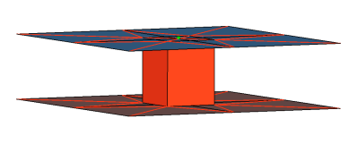
Creates a hexa element with DCOUP3D elements projecting and connecting to the
surrounding shell elements. This realization does not use the shell thickness to
calculate the hexa offset, therefore the hexa will project and be touching the shell
elements.
This realization uses the prop_abaqus_acm.tcl4 property script. Figure 19.
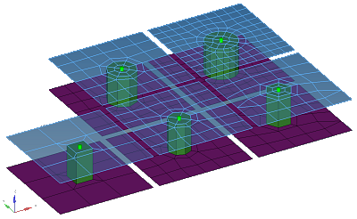
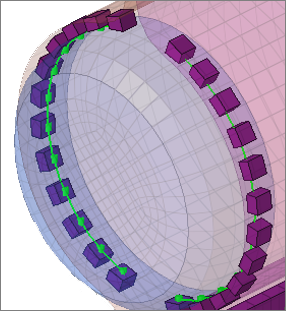
Creates one hexa cluster per connector and realizes a node to node connection to the
linked shell meshes by adjusting it (shell coating). Different patterns are available.
This is driven by the number of hexas. The appearance can be influenced via the diameter
and the washer layer activation. Figure 20.
Consolidates several ACM definitions into one general, flexible ACM definition.
Besides mid thickness, constant thickness, and maintain gaps, the definition of several
coats with different hexa patterns is available.
This realization uses the prop_abaqus_acm.tcl4 property script. Figure 21.
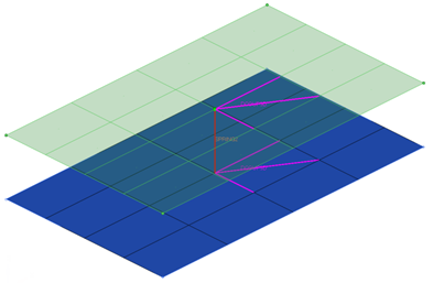
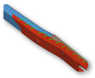
Creates a quad row with tria caps at the seam ends. In addition, a certain pure quad
element pattern is created around the seam elements, shown here in red. These elements
normally get imprinted into the shell links. The exact geometry of the seam can be
influenced by certain attributes in the Seam panel.
This realization is mainly intended to be used for lap welds.
Note: You can revert the
direction of quad seam connectors during the next realization by activating the
reverse direction checkbox in the Seam panel.
Description: Creates two quad rows-the first one perpendicular to the opposite shell
link, and the second one with a certain angle to the first one. In addition, a certain
pure quad element pattern is created around the seam elements, shown here in red. These
elements normally get imprinted into the shell links. The exact geometry of the seam can
be influenced by the angle value.
This realization is can be used for both lap- and T-welds.
Note: You can revert the
direction of quad seam connectors during the next realization by activating the
reverse direction checkbox in the Seam panel.
Creates one quad row under a certain angle. The angle is measured between the quad row
and the perpendicular projection from the free edge to the opposite shell link. In
addition, a certain pure quad element pattern is created around the seam elements, shown
here in red. These elements normally get imprinted into the shell links. The exact
geometry of the seam can be influenced by the angle value.
This realization is can be used for both, lap- and T-welds.
Note: You can revert the
direction of quad seam connectors during the next realization by activating the
reverse direction checkbox in the Seam panel.
Creates SPRING elements for the body, and projects and connects to the adjoining
shell/solid elements with DCOUP3D elements.
The realization uses the prop_mastic.tcl2 property script. Figure 26.
CFG abaqus 105 Mastic
*filter spot
*head
rbe3 1 0
*body 0
spring 1 1
spring 1 1
spring 1 1
*post prop_mastic.tcl
Abaqus hexa (adhesive)
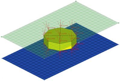
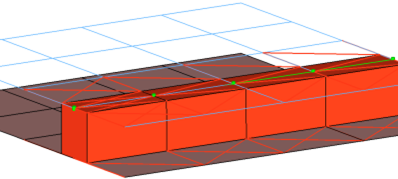
Creates a row of hexa elements for the body, and numerous DCOUP3D elements for the
head. The head elements project and connect to the nodes of the adjoining shell/solid
elements. The hexa elements are projected so that they touch the shell/solid elements of
the connecting components.
This realization also uses the prop_abaqus_acm.tcl4 property script. Figure 27.
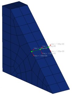
Creates perpendicular and parallel vectors to the surface along a line/nodelist. On
exporting the connector file, a vector file (.asc format)
containing the vector information is also exported for this realization. Figure 28.
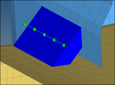
Intended to be used for t-cases. The size and exact position can be defined thickness
dependent, or the exact dimension and position parameters can be given. Figure 29.
Creates a Node Set that contains the nodes that are selected to create the connector
element, and creates an empty Element Set. Connector elements are not created for this
realization type. Abaqus creates the required connector
elements on its own.
This realization uses the prop_fastener_nodes.tcl1 property script. Figure 30.
Figure 31.
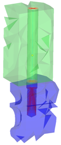
This realization creates a B31 element for the bolt shaft and connects to the
solids' nodes with numerous KINCOUP rigid elements based on the given bolt/hole
parameters. It connects two solids through holes, or it connects one solid through a
hole with a solid blind
hole.
Connects two solids through holes, or connects one solid through a hole with a solid
blind hole. A thread length can be defined to define the dimensions of the rigid
elements connecting the bolt shaft models as a bar. Figure 32.
Creates hexa (C3D8) elements between shell and/or solid elements in order to connect
them using a tie contact definition. The hexa element nodes will project and touch the
shell and/or solid element faces. During the realization, a default tie contact and
referencing main and secondary surfaces are created; unless defined differently, the hexas
are assigned a default property and material, and are organized into a component with
the same name base as the property.
The default tie contact and material parameters can be changed in the files below this
path: ..\Altair\2021\hm\scripts\connectors\Hexa_Tie\abaqus\.
Note: IDs, names, and card type
cannot be changed.
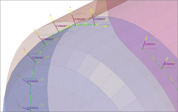
Creates rod (CONM3D2) elements between shell and/or solid elements in order to connect
them using a tie contact definition. The rod element nodes will project and touch the
shell and/or solid element faces. During the realization, a default tie contact and
referencing main and secondary surfaces are created; unless defined differently, each rod
is assigned a property, which references a default material (CONNECTOR BEHAVIOR) and an
individual coordinate system. By default, the property is directly assigned to the
element so that all rods can be hosted in one component.
The default tie contact and material parameters can be changed in the files below this
path: ..\Altair\2021\hm\scripts\connectors\Rod_Tie\abaqus\.
Note: IDs, names, and card type
cannot be changed.
Figure 34.
CFG abaqus 153 rod (spot tie)
*filter spot
*style spot_tie 3
*head
*body 0
rod 13 1
Abaqus hexa (seam tie)
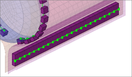
Creates hexa (C3D8) elements between shell and/or solid elements in order to connect
them using a tie contact definition. The hexa element nodes will project and touch the
shell and/or solid element faces. During the realization, a default tie contact and
referencing main and secondary surfaces are created; unless defined differently, the hexas
are assigned a default property and material, and are organized into a component with
the same name base as the property.
The default tie contact and material parameters can be changed in the files below this
path: ..\Altair\2021\hm\scripts\connectors\Hexa_Tie\abaqus\.
Note: IDs, names, and card type
cannot be changed.
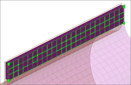
Used while creating Abaqus Fasteners-Nodes in the Spot panel. It performs the
following tasks:
Organizes the realized weld elements into their respective components, based
upon the link they are connected to. Thus, if a weld is created between comp_1(1)
and comp_2(2), the script creates a component collector with the name
HM_HMCONN_<id> and organizes all the welds (Dummy element) created as links
between these two components into this collector. This collector is later
referenced as the element set while creating Groups (Interfaces).
Creates groups with the card image *FASTENER, and assigns them the name
HM_FastenerInteraction_<id>. The fastener connects two component collectors and
refers to the fastener property card. The Automatic_Surface_from_components option
is used to show the elements to which the weld elements are linked to.
Creates the following properties/material collectors:
HM_ConnectorBehavior<id>
This material collector is created with the *CONNECTOR BEHAVIOR card
assigned to it.
HM_FastenerProperty_r_<radius in property>
This property collector is created with the *FASTENER PROPERTY card
assigned to it.
HM_ConnectionSection_<id>
This property collector is created once per model (card image *CONNECTOR
SECTION). The property is assigned to each HM_CONN3D2 component collector
and carries the material HM_ConnectorBehavior.
Creates the following sets:
HM_FastenerNodes_Node_Set1
Contains the selected nodes for the Fastener.
HM_HMCONN_<id>
This is the dummy elset. The connector element is created and collected
based on the nodeset HM_FastenerNodes_Node_Set1 assigned to this elset. You
can refer the elset to outputblock.
prop_mastic.tcl
Performs the following tasks:
Organizes the SPRING elements into components with the names SPRING_X, SPRING_Y
and SPRING_Z.
Organizes the DCOUP3D elements into the component DCOUP_3D_no_prop.
Creates properties with the SPRING card image, and names the properties
spring_prop_K1_ElemId-##, spring_prop_K2_ElemId-##, and spring_prop_K3_ElemId-##
(where ## is the element ID of the SPRING element).
Note: New components will only
be created if their are not any components with the same names that already
exist; otherwise the existing components are used.
prop_abaqus_b31.tcl
Updates the direction nodes of a group of
bar elements created during realization to use the y axis. The
*bardirectionupdate command is called to update the orientation
node of bar element along Y-axis.
prop_abaqus_acm.tcl
Used while creating acm
(equivalenced-(T1+T2)/2) / (detached-(T1+T2)/2) /shell gap in the Spot panel and
adhesives in the Area panel. It performs the following tasks.
Organizes the realized weld elements [acm Equivalence-(T1+T2/2)] into the
respective components based upon the *HEAD and the *BODY information of the weld.
During realization of this configuration type a solid hexa element [C3D8] is
connected to the shell elements by the rbe3 elements [DCOUP3D].
A collector with the name C3D8_comp_<id> is created with the SOLIDSECTION
card image associated with it. This component contains all of the solid C3D8
elements which are created during realization.
A collector with the name DCOUP3D_comp_<id> is created, containing all of
the DCOUP3D elements created as the heads to the weld element.
If this script is called during the realization of adhesives in the Area panel,
this script creates the above two components by different names:
hexa_comp_<id>
For the Hexa elements
rbe2_comp_<id>
For the rbe elements
The script also creates a property collector named prop_<id>, with the
SOLIDSECTION card image associated to it. This property collector is referenced to
the component containing the Hexa elements created during realization process
(i.e. C3D8_comp_<id> in the case of spots, or hexa_comp_<id> in the case of
adhesives).
prop_fastener.tcl
Used while creating Abaqus Fasteners in the Spot panel. It performs the following
tasks.
Organizes the realized weld elements into their respective components, based
upon the link they are connected to. Thus, if a weld is created between comp_1(1)
and comp_2(2), the script creates a component collector with the name
HM_CONN3D2<id> and organizes all the welds created as links between these two
components into this collector. This collector is later referenced as the element
set while creating the Groups (Interfaces).
Creates the following properties/materials collectors:
HM_ConnectorBehavior<id>
This material collector is created with the *CONNECTOR BEHAVIOR card
associated with it.
HM_ConnectionSection_<id>
This property collector is created once per model (card image CONNECTOR
SECTION). The property is assigned to each HM_CONN3D2 component collector
and carries the material HM_ConnectorBehavior.
HM_FastenerProperty_r_<radius in property>
This property collector is created with the *FASTENER PROPERTY card
associated with it. It defines the RADIUS and the degree of freedom
definition of the fastener.
Creates Groups (HM Interfaces) with the name HM_FastenerInteraction<id> and
with the *FASTENER card associated with it. The fastener connects two component
collectors and refers to the fastener property card mentioned above. It can also
show the link elements to which the weld elements are linked via the
Automatic_Surface_from_components option.
If any system option (Single System ,1- System per layer or 2- Systems per
layer) is used in the Spot panel during realization, this script creates
ORIENTATION systems in the current collector with the name
HM_ORI<weld_id>_n<node_id>. A property HM_ConnectorSection_<CONN3D2
element id> is created and assigned per element. Depending on whether one or
two systems per layer are created the property points to one or both
systems.
prop_cylinder.tcl
Used while creating bolt (cylinder rigid)
and bolt (cylinder bar) in the Bolt panel (Abaqus,
Nastran, OptiStruct). It
organizes the realized bolt elements into the respective components based upon
the*HEAD and the *BODYinformation of the bolt:
A collector with the name Rigid_M<diameter> is created. This component
contains all of the rigid head elements and the rigid body elements, if
available.
A collector with the name Beam_M<diameter> is created. This component
contains all of the bar2 head elements, if available. This component then gets a
property Beam_M assigned (*BEAMSECTION or PBEAM).