Graphical Selection
Select and deselect entities to modify with other HyperLife tools. Selected entities are outlined to indicate their selection state.
Hover over an entity to highlight it.
In idle mode, entities can be selected from either the modeling window or the browser area. Selecting an entity in the modeling window automatically selects the corresponding entity in the browser and vice versa.
When working in a tool, entities should be selected from the modeling window.
Entity Selector
Use the entity selector to specify which type of entity you are able to select.
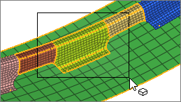
In idle mode, the entity selector limits your selection to a single entity type in the modeling window. For example, if the entity selector is set to Elements, only elements are available for selection. If it is set to Nodes, you can draw a window around the entire model and only the nodes will be selected. After performing a selection, the number of selected entities appears in parenthesis.
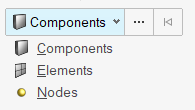
Figure 1.
The entity selector does not affect your selection in a browser. You're also able to select multiple entities of different types in a browser.
When working in a panel, the entity selector in the modeling window is disabled and the yellow panel selectors take precedence.
- Use keyboard shortcuts to change the active entity type in the entity selector.
- Convert your selection to a new entity type by changing the entity selector. For example, if you select elements, and then set the entity selector to nodes, all of the nodes associated with the selected elements will be selected.
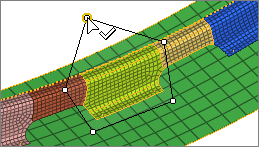
Select Single Entities
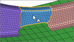
Figure 2.
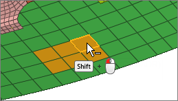
Append and Remove Entities From a Selection
-
In the modeling window:
- Append entities to your selection by holding Ctrl while left-clicking.
- Remove entities from your selection by holding Shift while left-clicking.
Figure 3.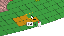
-
Clear your selection in the following ways:
- Left-click in empty space.Note: Only available in idle mode.
- Click
 on the entity selector
 - Press Esc.
- Left-click in empty space.
Select Multiple Entities Simultaneously
- For box, circle, or freehand selection, click-and-drag to draw a selection window.
- For polyline selection, click-and-drag to draw a line, then release the mouse to create an end point. Continue drawing lines, then left-click the start point, middle-mouse-click, or press Enter to close the selection window.
 |
 |
Window Selection Settings
Change window selection settings from the modeling window right-click context menu.
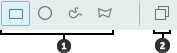
Figure 5.
- Window Shape. Change the shape of the selection window when you drag your mouse.
- Only Select Visible. Only select visible entities. Available for elements.
Perform Extended Entity Selection
Use extended entity selection to find, filter, and select subsets of entities. You can also save and retrieve previous selections.
-
Use the Advanced Selection dialog, which can be opened in
the following ways:
- Click
 next to an entity selector.
 - Press Spacebar.
- Right-click in the modeling window and choose .
Pick a selection method from the drop-down menu in the top-left of the dialog then select a subset of entities.The process for selecting entities varies depending on the method.
Tip: The options in the context menu beneath Advanced (By Entity, By ID, etc. ) correlate to different selection methods in the Advanced Selection dialog. Choosing one of these options opens the dialog with the selected method. - Click
Extended Entity Selection Options
The following options are available for extended entity selection.
Context Menu Options
- Displayed
- Select all entities of the specified type currently displayed in the modeling window.
- Reverse
- Allows for a Boolean "not" to be performed on the currently displayed entities; all selected entities are removed from the mark; all entities which are not on the mark and are currently active are selected.
- All
- Select all entities of the specified type. The set to be added to the user mark includes entities displayed and those not displayed.
- Adjacent
- Select entities adjacent to the entities already selected.
- Attached
- Select entities by specifying an entity among a large group of continuously connected elements. HyperLife includes the entities currently displayed that are attached to the entities already selected. Entities that are not displayed will not be selected although they may be attached to the entity selected.
- Face
- Select nodes/elements that are located on the same face as the previously selected entity. A face is defined as a region on the model surface where the angle between element normals does not exceed a certain threshold. This threshold is controlled by the Feature angle setting.
- By Dimension
- Select entities by dimension (0D, 1D, 2D, and 3D). You can select one or more of the dimensions available.
- Save Selection
- Save the currently selected entities to a holding area known as the user mark.
- Retrieve Selection
- Retrieve previously saved entities from the user mark.
Advanced Selection Dialog Options
All selection methods in the dialog include a visibility filter. This allows you to apply your settings to all entities in the model, regardless if they are displayed on the screen or not, or only the entities that are displayed.
In addition,HyperLife is capable of entity binding changes between nodes, elements, and components - which provides you with easy selection. For example, when Nodes is specified on the entity selector, the By ID option allows you to select either By Node ID, By Element ID, or By Component ID.
- By ID
- Select entities by entering an ID number.
- By Type
- Select elements by configuration. You can select one or more of the various element configurations available.
- By Sets
- Select the entities within a set.
- By Contour
- Select entities by contour.
- By Sphere
- Allows you to select entities by entering location information for x, y, z and a user-defined radius.
Keyboard Shortcuts & Mouse Controls
Selection
| To do this | Press |
|---|---|
| Window select | Left Mouse Drag |
| Append selection | Ctrl + Left Mouse Click |
| Deselect | Shift + Left Mouse Click |
| Select displayed | Ctrl + A |
| Select adjacent | Ctrl + J |
| Reverse selection | Ctrl + R |
| Clear selection | Esc |
Entity Selector
| To do this | Press |
|---|---|
| Set to components | C |
| Set to elements | E |
| Set to nodes | N |
Select Entities Using the Input Collector
When working in a panel or the Entity Editor, selection is performed via yellow input collectors.
Input collectors allow you to select entities in a model to which you can apply various tool functions. Their behavior is similar to the entity selector in the modeling window.
An input collector contains an entity type selection switch, an entity type button, and a reset button. An input collector is active when the entity type button is enclosed in a blue rectangle, as shown in the image below.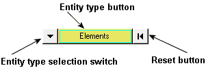
Figure 6. Input collector – elements selected
- Nodes
- Nodes
- Elements
- Elements
- Components
- Components
- Assemblies
- Hierarchical component sets
- Systems
- Local coordinate system
- Picking entities from the modeling window.
- Using quick window selection.
- Using the extended entity selection menu.
An input collector entity type in the plural form, such as "elements", indicates that you are able to select more than one entity from your model. An input collector entity type in the singular form, such as "node", indicates that you can select only one entity from your model at a time.
When you need to define a plane by specifying a plane's normal vector, the input collector allows you to select nodes one at a time by entering the node ID. Similar to the standard input collector described earlier, the active node is surrounded by a blue square. Click the entity type selection switch to change the input collector type, and click the reset button to reset the input collector.
Examples of this type of input collector include:

Figure 7. Plane normal vector definition using the global axis

Figure 8. Plane normal vector definition
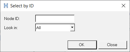
Figure 9. Select by ID dialog
- Look in
- Allows you to select which pool contains the entity. For example in the case of elements, ID 1 could be in the Shell pool or the Solid Pool (if the model has duplicated IDs), therefore you would need to specify a pool for selecting a unique entity.
- All
- All of the entities with duplicate IDs are selected.
Use the Extended Entity Selection Menu
-
From a panel or
the Entity Editor, click the entity type button
on the input collector
 to access the extended entity
selection menu.
A pop-up menu containing the available selection techniques is displayed. This menu allows alternative methods for selecting elements of the specified entity type.Note: The options displayed on the extended entity selection menu are dependent upon the active input collector.
to access the extended entity
selection menu.
A pop-up menu containing the available selection techniques is displayed. This menu allows alternative methods for selecting elements of the specified entity type.Note: The options displayed on the extended entity selection menu are dependent upon the active input collector.
Extended Entity Selection Menu
The extended entity selection menu provides a number of entity selection options.
Figure 10. Input collector – elements selected
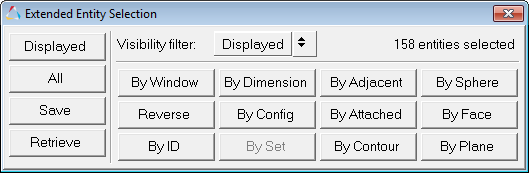
Figure 11. Extended entity selection menu for the Elements entity type
You can then select an option from the extended entity selection menu. The above image shows all the selection options available in HyperLife. However, not all entity types offer all the selection options. Only valid selections for the current entity type are displayed on the menu. For instance, if you are using the Systems input collector, the By Config, By Dimension, By Sphere, and By Set (Group) entity selection options are not available.
- By right-clicking in the modeling window.
- In the Advanced Selection dialog by clicking on the entity selector.
- Displayed
- Select entities that are currently displayed in the modeling window for the specified types.
- All
- Select all entities in a model of the specified type. When you select All, the set to be added to the user mark includes entities displayed and those not displayed.
- Save
- Save the current selected set of entities for future use.
- Retrieve
- Retrieve the current saved selection set of entities
- Visibility filter
- This affects the following options:
- All
- Apply your settings to all entities in the model, regardless if they are displayed on the screen or not.
- Displayed
- Apply your settings to only the entities that are displayed on the model.
- By Window
- Select entities based on a user-defined multiple-sided polygon on the screen.
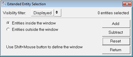
Figure 12. Extended Entity Selection -- By Window menu for the Elements entity typeUse Shift + left mouse button to define the window points. Select points in the modeling window to define a window enclosing the pick handles of the entities to select or exclude.- Select Entities inside the window to highlight the entities within the window.
- Select Entities outside the window to highlight entities outside of the window.
- Reverse
- Allows for a Boolean "not" to be performed on the currently selected entities. When Reverse is selected, all selected entities are removed from the mark; all entities that are not on the mark are selected.
- By ID
- Select entities by entering an ID number.
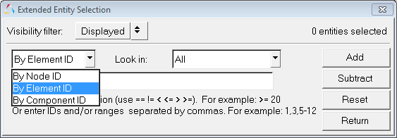
Figure 13. Extended Entity Selection -- By ID menu for the Elements or Nodes entity typeMake a selection from the By ID drop-down menu (By Node ID, By Element ID, or By Component ID), and then enter a valid expression (listed below) and an ID in the text box.
- ==
- Displays entities equal to the ID entered
- !=
- Displays entities not equal to the ID entered
- <
- Displays entities less than the ID entered
- <=
- Display entities less than or equal to the ID entered
- >
- Displays entities greater than the ID entered
- >=
- Display entities greater than or equal to the ID entered
- By Dimension
- Select entities by dimension (0D, 1D, 2D, and 3D). You can select one or more of the
dimensions available.
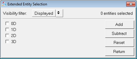
Figure 14.Setting the input collector to Nodes allows you to select nodes attached to all elements with the selected dimension. HyperLife performs the entity binding changes for proper selection.
- By Config
- Select elements by configuration. You can select one or more of the various element
configurations available.
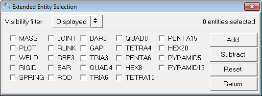
Figure 15.If Element configuration is selected, HyperLife will apply the binding changes to find the nodes connected to the elements.
- By Set
- Select from a drop-down menu of created sets/groups.
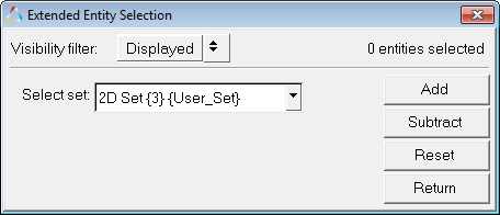
Figure 16. - By Adjacent
- Select entities adjacent to the entities already selected. When you select By Adjacent, HyperLife includes the entities that are adjacent to the entities already selected.
- By Attached
- Select entities by specifying an entity among a large group of continuously connected elements. When you select By Attached, HyperLife includes the entities that are attached to the entities already selected.
- By Contour
- Select entities by contour.
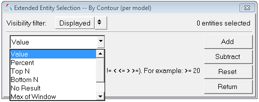
Figure 17.The following contour options are available:- Value
- Enter a contour value in the text box (see the Note below).
- Percent
- Enter the percentage of entities to select (0 to 100) in the text box (see the Note below).
- Top N
- Enter a positive decimal value for N, where N is the number of entities to be selected. For example, if you enter 50, the application displays the top 50 elements/nodes that have the highest contour value.
- Bottom N
- Enter a positive decimal value for N, where N is the number of entities to be selected. For example, if you enter 50, the application displays the bottom 50 elements/nodes that have the lowest contour value.
- No result
- All nodes or elements without any results are selected.
- Max of Window
- Displays the maximum contour value for the entities defined using the Quick Window Selection feature (Shift + left mouse button).
- Min of Window
- Displays the minimum contour value for the entities defined using the Quick Window Selection feature (Shift + left mouse button).
Note: If you select Value or Percent, you must select a quantifier from the bottom, left-most drop-down menu:- =
- Displays entities equal to the contour value/percent entered.
- !=
- Displays entities not equal to the contour value/percent entered.
- <
- Displays entities less than the contour value/percent entered.
- <=
- Display entities less than or equal to the contour value/percent entered.
- >
- Displays entities greater than the contour value/percent entered.
- >=
- Display entities greater than or equal to the contour value/percent entered.
- By Sphere
- Allows you to select entities by entering location information for x, y, z and also
entering a user-defined radius.

Figure 18. - By Face
-
Select nodes/elements that are located on the same face as the previously selected entity. A face is defined as a region on the model surface where the angle between element normals does not exceed a certain threshold. This threshold is controlled by the Feature angle setting. This works on both shell and solid elements.
Limitations:- Does not handle flipped normals.
- Cannot be used to select components.
- By Plane
- Select nodes/elements that lie within a certain tolerance (in model units) of the
defined plane. This selection method uses a vector input collector (X Axis, Y Axis, Z
Axis, Vectors, N1N2N3, Normal to screen).
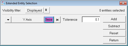
Figure 19.
- Add
- Adds entities to the selection set that satisfy the user-defined criteria.
- Subtract
- Removes entities from the selection set that satisfy the user-defined criteria.
- Reset
- Removes the selections made and returns the model to its original state.
- Return
- Returns to the main panel.
- Apply
- After defining the entity selection set, click Apply to
select the entities, apply the desired action, and return to the previous panel.A default action is one of the following:
- Create a vector plot (if invoked from the Vector panel).
- Create a tensor plot (if invoked from the Tensor panel).
Change the Entity Type
-
From a panel or
the Entity Editor, click the entity type
selection switch
 to access the pop-up menu of
possible entity types.
to access the pop-up menu of
possible entity types.
- Select the type that you want to use.