| Note: | To accept selection(s), press Enter, click Yes or right-click the mouse button; or select Cancel. |
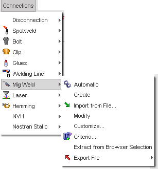
Automatic creation
All the uncreated Mig welds can be created automatically:
| • | Open the Connections > Mig Weld > Automatic. |
Manual creation
| • | Select Mig Weld > Create. |
Part selection
Button
|
Behavior
|

|
pick two parts in the graphic window (the parts become red).
|

|
to include two parts by dragging a box in the graphic window:
| • | The default box is rectangular. |
| • | Use the SHIFT key to define a polygon box. |
|

|
to include the two parts selected in the tree.
|
To create a Mig weld with the same part two times, first select the part (it becomes red) and then, using the SHIFT key, select the same part one or more times (it becomes yellow).
Set the position of the Mig weld
Four options are available to set the position of the Mig weld:
| 1. | Select the Element tab. |
| • | Click  and select an element in the graphic window. and select an element in the graphic window. |
| • | Set an element ID in the Shell Element Id field and click Ok. |
| • | Click Save to save the created Mig weld(s). |
| • | Click Cancel to cancel the Mig weld creation. |
| • | If necessary, select another element to create another Mig weld. |
| • | Click Close to close the menu. |
| • | Click  and select a node in the graphic window. and select a node in the graphic window. |
| • | Click  and pick anywhere on a selected part to define the Mig weld location at the same point. and pick anywhere on a selected part to define the Mig weld location at the same point. |
| • | Set a node ID in the Node Id field and click Ok. |
| • | Set the coordinates X, Y, and Z and click  to view the point. to view the point. |
| • | Click Save to save the created Mig weld(s). |
| • | Click Cancel to cancel the Mig weld creation. |
| • | If necessary, select another node to create another Mig weld. |
| • | Click Close to close the menu. |
| • | Click  to view where the Mig weld can be created. HyperCrash displays the areas of the selected parts where Mig weld can be created in dark blue. to view where the Mig weld can be created. HyperCrash displays the areas of the selected parts where Mig weld can be created in dark blue. |
| • | Enter the length between two Mig welds in the Pitch length field and click Ok. |
| • | Click and select two elements in the graphic window in order to define the beginning and the end of the Mig weld. |
| • | Click and select two nodes in the graphic window in order to define the beginning and the end of the Mig weld. |
| • | Click and pick two points anywhere on a selected part to define the beginning and the end of the Mig weld. |
| • | Click Save to save the created Mig weld(s). |
| • | Click Cancel to cancel the Mig weld creation. |
| • | If necessary, select two other nodes to create another Mig weld. |
| • | Click Close to close the menu. |
| • | Enter or modify the search gap value. |
| • | Click to view the Mig weld creation. |
| • | Click to change the part used to define the Mig weld locations. |
Save the created Mig weld
| • | Click Save to save the created Mig weld(s). |
| • | If necessary, select another element, node or line according to the active position setting mode. |
| • | Click Cancel to cancel the Mig weld creation. |
| • | If necessary, set a position to create new Mig weld(s) using elements, node or line selection. |
| • | Click Close to close the menu. |


