Create a seat belt
| 1. | From the Menu Bar, select Safety > Belt Generator. |
| 2. | Enter a name in the Belt field and validate with Ok. |
| 3. | Click Type and select one of the following: |
| • | Shells to create a belt with shell elements. |
| • | Multi-strand to create a belt with multi-strands. |
| • | Truss to create a belt with truss elements. |
| • | Spring_3n to create a belt with a 3-nodes spring element. |
| 4. | Click Options and select one of the following: |
Node selection
| 1. | Click  for seat belt reference points. for seat belt reference points. |
| 2. | In the Belt Position defined by Nodes window, click  . . |
| 3. | In the graphic window, click a few nodes to define the belt trajectory. For Spring_3n belt type, select only three nodes. |
| 4. | Click Cancel in the Dialog menu bar to stop the node selection. The node list is updated. |
If necessary, it is possible to move the selected nodes one-by-one:
| • | Select a node in the node list. |
| • | Click  . . |
| • | Modify the X, Y, and/or Z coordinate(s). |
| • | Click Apply to validate the modification, or Cancel to cancel it. |
If necessary, it is possible to move all the selected nodes:
| • | Click  . . |
| • | In the dX, dY, and dZ fields, enter the node displacement to apply. |
| 5. | Click Apply to validate the modification, or Cancel to cancel it. |
| 6. | Click OK to validate the node selection. |
Part selection
The dummy parts on which the belt will be leaned must be selected. Use one of the following methods:
| 1. | Click  and pick parts of the dummy in the graphic window. When finished, answer the question in the Dialog menu bar with Yes or Cancel. and pick parts of the dummy in the graphic window. When finished, answer the question in the Dialog menu bar with Yes or Cancel. |
| • | Click  to add the dummy parts selected in the tree. to add the dummy parts selected in the tree. |
| • | Click  to add parts of the dummy by box selection: to add parts of the dummy by box selection: |
| o | The default box is rectangular. |
| o | Use the SHIFT key to define a polygon box. |
| • | Click  to remove parts of the dummy by box selection: to remove parts of the dummy by box selection: |
| o | The default box is rectangular. |
| o | Use the SHIFT key to define a polygon box. |
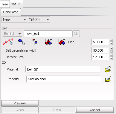
Belt components
| • | Gap between the dummy and the belt (Shells and Truss belt types only): |
| o | Set the gap value in the Gap field. |
or
| o | Click  to modify the gap. to modify the gap. |
| • | Belt width (Shells belt type only): |
| o | Set the belt width in the Belt geometrical width field. |
or
| o | Click to modify the belt width. |
| • | Number of shell elements in the length (Shells and Truss belt types only): |
| o | Set the number of shell elements in the Nb elems in length field. |
or
| o | Click to modify the number of shell elements. |
| • | Number of shell elements in the width (Shells belt type only): |
| o | Set the number of shell elements in the Nb elems in width field. |
or
| o | Click to modify the number of shell elements. |
| • | Transversal direction at the first node: This defines the belt perpendicular direction at the first node (Shells belt type only): |
| o | Click the X, Y or Z radio button. |
or
| o | Click the first  button and, in the graphic window pick a node. Next, click the second button and, in the graphic window pick another node to define the direction. button and, in the graphic window pick a node. Next, click the second button and, in the graphic window pick another node to define the direction. |
or
| o | Fill in the two X, Y, and Z fields defining the direction. |
| o | Click  to display the direction in the graphic window. to display the direction in the graphic window. |
| • | Transversal direction at the last node: This defines the belt perpendicular direction at the last node (Shells belt type only): |
| o | Click the X, Y or Z radio button. |
or
| o | Click the first button and, in the graphic window pick a node. Next, click the second button and, in the graphic window pick another node to define the direction. |
or
| o | Fill in the two X, Y, and Z fields defining the direction. |
| o | Click to display the direction in the graphic window. |
| • | Material (Shells and Truss belt types only): |
| o | Click  . . |
| o | In the Material File window, select the desired material (law 2 for Shells type, law 1 for Truss type) and click OK. |
| o | The stress vs. strain curve appears on the screen. To confirm, click Yes in the Dialog menu bar. |
| o | Click . |
| o | In the Property File window, select the desired property and click OK. |
Belt creation
| 1. | Click See to display the defined belt. |
| 2. | If necessary, the following can be modified: |
| 3. | Once the belt is finished, click Save to save it. |
or
Click Cancel to cancel the belt creation.
| 4. | Click Close to close the menu. |
Modify a seat belt
| 1. | From the Menu Bar, select Safety > Belt Generator. |
| 2. | Click Belt list and select a created belt. Follow the same steps as with Belt creation. |
Delete a seat belt
In the tree window, select the seat belt part and delete it as with a normal part. The model and the seat belt menu will be automatically updated.
See also
Dummy Positioner
Seat Deformer


