Dummy Positioning
Position a dummy model using the Dummy Browser.
Dummy Browser
Overview of the Dummy Browser.
From the menu bar, click .
This browser is compatible with all LS-DYNA and Radioss Humanetics dummies (encrypted or not encrypted) and also with LSTC dummies.
You can undo and redo actions made in the browser using the Undo and Redo commands on the Restore toolbar.
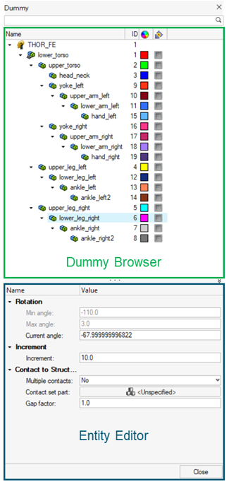
Figure 1.
| Column | Description |
|---|---|
| Entity | List of the dummies and dummy bodies. |
| ID | Displays the dummies and bodies IDs. |
| Color | Displays the body entity colors. Body color is different from the component color defined in the Model Browser. The body color is activated when a body is in Review mode or when display mode is set on “By Body”. |
Entity Editor
The Entity Editor is used to assign, modify and quickly view the attributes defined inside Dummy Browser entities.
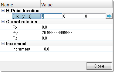
Figure 2.
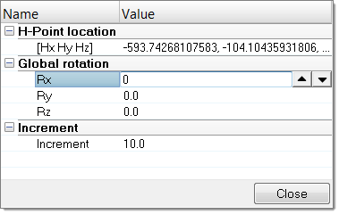
Figure 3.
The Entity Editor is also used to modify the position of bodies. You can directly define the angle of rotation to apply in each axis of rotations in which the selected body is able to move.
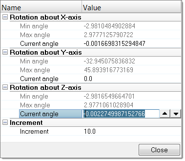
Figure 4.
Context Menu
Supported Entities
The Dummy (![]() ) is the root of the
hierarchy in the Dummy Browser. A dummy is defined by bodies
(
) is the root of the
hierarchy in the Dummy Browser. A dummy is defined by bodies
(![]() ) representing the
different kinematic assemblies of the dummy.
) representing the
different kinematic assemblies of the dummy.
Position Dummies
Position the Body Manually
-
In the graphics area, click-and-drag the manipulator to interactively modify
the position of the selected body.
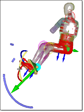
Figure 5.
Position the Body Automatically
-
In the Dummy Browser, right-click on a body and select
Move Limbs from the context menu.
The Entity Editor opens.
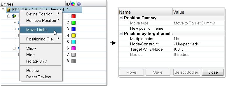
Figure 6. -
Click Select Bodies to open the Dummy Bodies
DOF dialog and select the bodies and degrees of freedom of the
active bodies that will be able to move during automatic positioning.
Select bodies by activating their corresponding checkbox, or picking them in the graphics area (right-click or left-click to activate/deactivate a body). Lock/unlock degrees of freedom by clicking the lock icon, or by picking the DOF arrows in the graphics area (right-click or left-click to activate/deactivate a DOF).
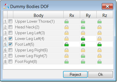
Figure 7.
Setup Pre-Simulation
Export an input deck to simulate the deformation of the dummy.
Figure 8.
The simulation result files can be imported to update the initial FE model and thus remove the intersections and penetrations between the dummy components.
- In the Dummy Browser, right-click and on the dummy and select Pre-Simulation from the context menu.
-
In the PreSimulation Tool dialog, define settings
accordingly.
- Define PreSimulation Tool Options accordingly.
- Optional:
Import the simulation result file to update the initial model, which allows the
dummy node's coordinates to be updated and element initial stress state to be
defined.
- For LS-DYNA, click Import dynain File to find the .dynain file.
- For Radioss, click Import h3d File to find the .h3d file.
- Click Export.
The pre-simulation deck is exported to the specified location.
During the export process of the dummy pre-simulation deck, HyperMesh exports the complete dummy model only, positioned in the selected Reference Position, per default, the Initial Position of the dummy.
The method used for the pre-simulation is known as the “cable” method, which uses 1D elements connected to dummy bodies, in order to pull them from their initial position to their final position.
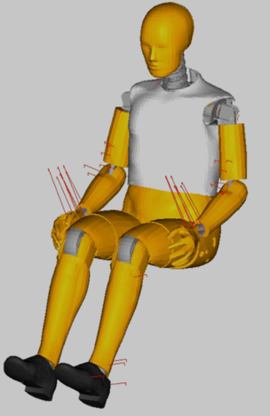
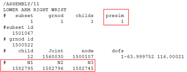
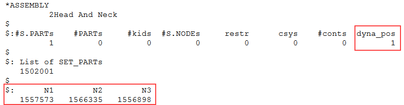
Figure 11. LS-DYNA
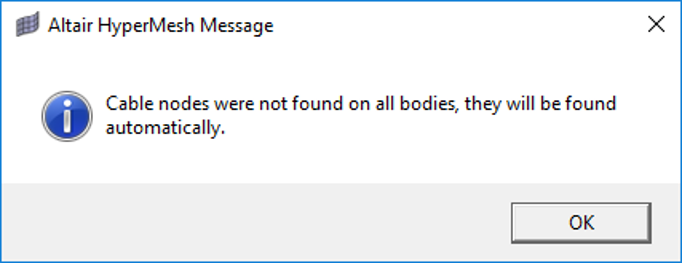
Figure 12. Altair HyperMesh Message
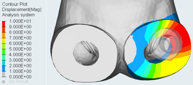
Figure 13.
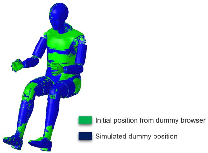
Figure 14.
PreSimulation Tool Options
Overview of supported options in the PreSimulation Tool.
LS-DYNA
- Simulation Parameter
-
- Simulation Time
- Define the total simulation time in *CONTROL_TERMINATION for the pre-simulation.
- Time Step
- Define the control time step value in *CONTROL_TIMESTEP for the pre-simulation.
- Force in cables
- Define the pre-tension force to be applied on the cable elements in *MAT_CABLE_DISCRETE_BEAM.
- Force ramp up time
- Define the ramp-up time for the pre-tension force in *MAT_CABLE_DISCRETE_BEAM.
- Damping on cables
- Define the damping value on the discrete elements in *MAT_DAMPER_VISCOUD.
- Global damping value
- Define the system damping constant in *DAMPING_GLOBAL.
- Initial Stress Results
-
- Import *INITIAL_STRESS_SOLID
- Import the initial stresses for solid elements from the .dynain file.
- Import *INITIAL_STRESS_SHELL
- Import the initial stresses for shell elements from the .dynain file.
- Import *INITIAL_STRESS_BEAM
- Import the initial stresses for beam elements from the .dynain file.
Radioss
- Simulation Parameters
-
- Generate XREF for initial stresses
- Create /XREF cards for the dummy components which are compatible with this RADIOSS feature in terms of material type and element formulation. The XREF cards are generated within the original session during the export of the pre-simulation deck, and not during import of .h3d file.
- Simulation time
- Define the total simulation time in /RUN card for the pre-simulation.
- Time Step
- Define the control time step value in /DT/NODA/CST card for the pre-simulation.
- Global damping value
- Define the system damping constant in /DAMP card.
- Create rigids for end bodies
- Automatically rigidify the end bodies (feet, hands, head) of the dummy during the pre-simulation.