NVH-1000: Acoustic Cavity
The model file used in this exercise can be found
in the es.zip file. Copy the file(s) from this directory to your
working directory.
Load the HyperMesh-Nastran, HyperMesh-OptiStruct or NVH-OptiStruct User Profile
-
Click the Load User Profile icon,
 , on
the Standard toolbar.
, on
the Standard toolbar.
- Click , or from the User Profiles dialog.
- Click OK.
Open the Model
-
From the menu bar, click or click the Open Model icon,
 , on the
Standard toolbar.
, on the
Standard toolbar.
-
Click Open to load the model.
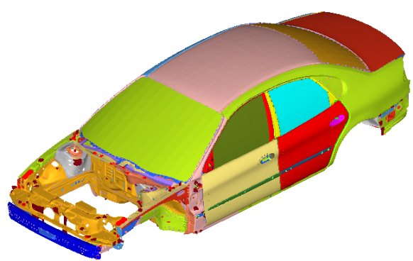
Figure 1.
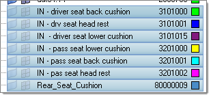
Hide the Seat Cushion Components
-
Select Rear_Seat_Cushion, IN-driver seat back
cushion, IN-drv seat head rest,
IN-driver seat lower cushion, IN-pass seat
lower cushion, and IN-pas seat head rest
from the list of components.
Set the Options for Creating Acoustic Cavity Mesh
The imported model has been restricted to just those parts that will be used to create the cavity. The seat cavities have already been built in this model.
-
Click the Options icon,
 , in the Acoustic Cavity toolbar.
The Options dialog opens.
, in the Acoustic Cavity toolbar.
The Options dialog opens.
Preview the Mesh
-
Click the
 icon in
the Acoustic Cavity toolbar.
icon in
the Acoustic Cavity toolbar.
-
Click preview to see a preview of the mesh.
The mesh appears in the graphics area and the Acoustic Cavity tab opens in the tab area. Note that the Front Door volumes are separate but trunk volume is a part of the overall cavity.
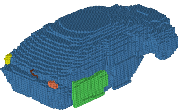
Figure 2. Preview of Mesh
Review the Mesh
-
Right-click AC_Structural.1 in the Acoustic Cavity tab
and click Isolate.
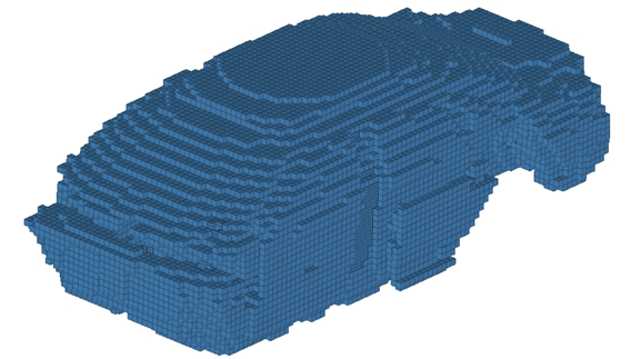
Figure 3. AC_Structural.1 Isolated -
Click the
 icon next
to each of the seat cavities to see the mesh.
icon next
to each of the seat cavities to see the mesh.
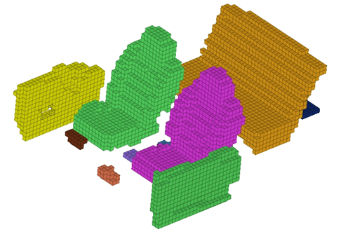
Figure 4. Seats Added to the Visible Components
Delete Two of the Patched Holes
-
Zoom into the area, as shown in the image below.
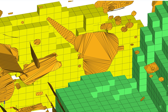
-
Delete the similar type of element patch on the other side.
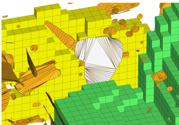
Figure 5.
Preview the Mesh
With the patched holes deleted, the acoustic cavity mesh will be previewed again.
-
Click the
 icon on the Standard Views toolbar to reset the view of
the model.
icon on the Standard Views toolbar to reset the view of
the model.
-
Click preview to preview the mesh.
The front door volumes are now a part of the overall volumes.
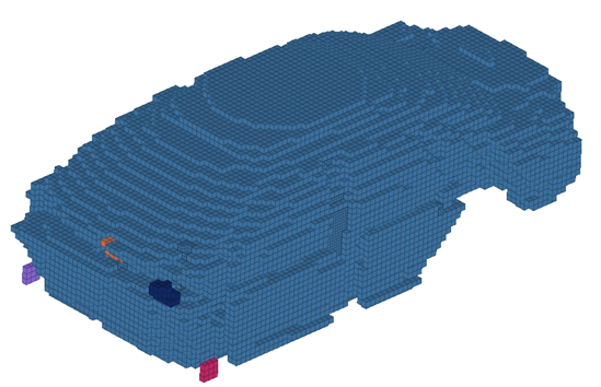
Figure 6.
Create a Patch Manually for Separate Volumes
-
Create a manual patch separating the trunk from the main volume.
A new component with the name Patch is created.
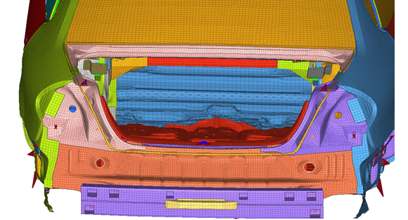
Figure 7. Connection Between Trunk and Main Volumes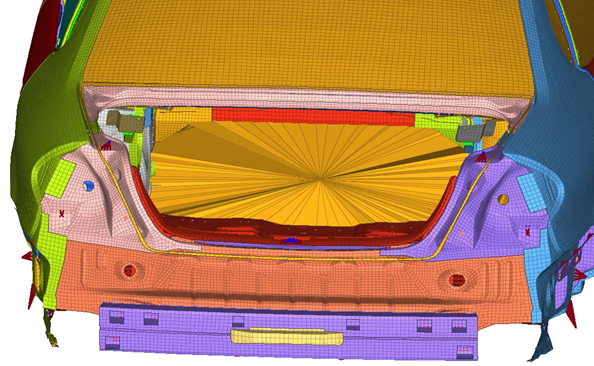
Figure 8. Patch Separating Trunk and Main Volume -
Click preview to preview the mesh.
The main cavity and the trunk cavity is separate. This way it is possible to create separate cavities.
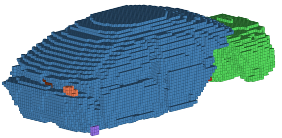
Figure 9.
Create the Mesh
-
Select AC_Structural.2 through
AC_Structural.10, right-click and select
Hide.
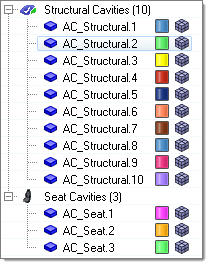
Figure 10. -
Click Mesh to create the mesh.
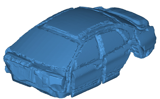
Figure 11. Completed Mesh
Rename the Components Created by the Acoustic Cavity Mesh
-
Name the component PASS_SEAT and press
Enter.
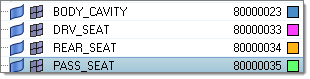
Figure 12.
Assign the Properties to the Components
-
For Property, click .
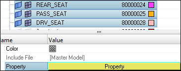
Figure 13. -
In the Model Browser, Component folder, select
BODY_CAVITY.
The Entity Editor opens.
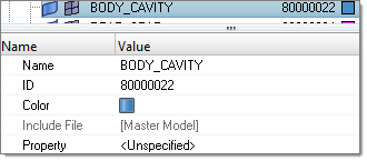
Figure 14. -
In the Select Property dialog, select
_int_prop and click OK.
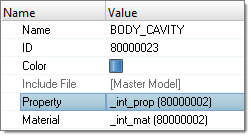
Figure 15.
Review Interface Between Structure and Cavity
-
Click the
 icon in the Acoustic Cavity toolbar.
-
Select the different types to Review interface and click
Show to review it.
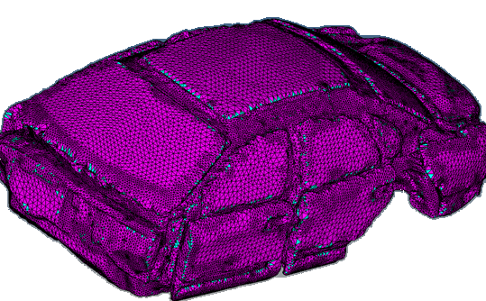
Figure 16.
Create MPCs
This step creates additional MPCs between different acoustic and structure components, if needed.
-
Click the
 icon in the
Acoustic Cavity toolbar.
The Create MPCs dialog opens.
icon in the
Acoustic Cavity toolbar.
The Create MPCs dialog opens.
Renumber the Nodes, Elements, Properties and Materials
- Click to open the Renumber panel.
- Click to select the displayed nodes.
- Enter 9000000 in the start with field.
- Click renumber to renumber the nodes.
- Change the selector to elems.
- Click to select the displayed elements.
- Click renumber to renumber the elements.
- Change the selector to props.
- Click props and select BODY_CAVITY and SEAT_CAVITY.
- Click renumber to renumber the properties.
- Change the selector to mats.
- Click mats and select BODY_CAVITY and SEAT_CAVITY.
- Click renumber to renumber the materials.
- Click return to exit the panel.