CFD-1200: CFD Meshing with Automatic BL Thickness Reduction
In this tutorial, you will learn to generate meshes for most CFD codes using the CFD
Tetramesh panel and generate boundary layer type meshes with arbitrary number of layers and
thickness distribution in domains defined by surfaces that are very close to one another in
some areas. More specifically, in some areas the clearance or separation of bounding
surfaces is not enough to accommodate the user specified nominal boundary layer thickness.
You will also learn to generate a distributed thickness “loading” that prevents boundary
layer interference/collision in zones where the distance between opposing walls is too small
to accommodate the baseline or nominal boundary layer thickness.
The model file
used in this exercise can be found in the es.zip file. Copy the
file(s) from this directory to your working directory.
Load the CFD User Profile
From the menu bar, click Preferences > User Profiles or click the Load User Profile icon,
, on
the Standard toolbar.
Click Engineering Solutions > CFD.
Click OK.
Open the Model File
On the Standard toolbar, click the Open Model
icon.
Select the manifold_inner_cylinder.hm file.
Click Open to load this file containing the surface
mesh.
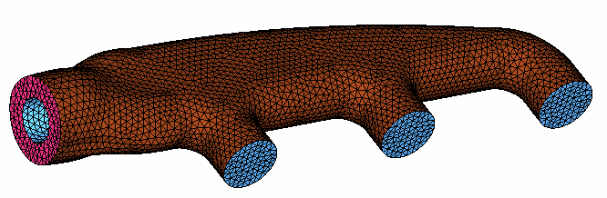
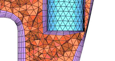
Figure 1.
Inspect the surface elements that will be used to generate the volume mesh. You
would like to generate boundary layers on all the surface elements contained in
components wall and wall_cyl. However, there is an area close to the end of
wall_cyl where the clearance between wall and wall_cyl is very small. This can
be easily observed in this case by changing the visibility of component wall, as
shown in the following image.
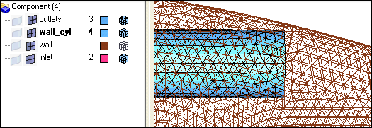
Figure 2.
In more complex models it is not possible to visually identify all the zones
where there is not enough space to growth the “baseline” or nominal boundary
layer as specified in terms of the number of layers, first layer thickness
and growth rate. This is not a problem because the automatic distributed
thickness “loading” computation takes into account all possible interference
cases. This is demonstrated in this tutorial.
Check That the Surface Elements Define a Closed Volume
Click Mesh > Check > Components > Edges.
Click comps and select all collectors that define the
domain’s surface, namely inlet,
outlets, wall and
wall_cyl.
Click find edges.
A message indicating that no edges were found appears on the status bar.
Toggle the free edges switch to
T-connections.
Select the components again and click find edges.
The status bar displays, “No T-connected edges
were found.”
Generate a BL Distributed Thickness Loading to Prevent Boundary Layer
Interference
Click Mesh > Volume Mesh 3D > CFD Tetramesh.
Click the Boundary selection subpanel.
Under the heading With BL (fixed), click comps and
select the collectors wall and
wall_cyl.
Under the heading W/o BL (float), click comps and select
the collectors inlet and
outlets.
Ensure that the switch below the W/o BL (float) selector is set to
Remesh.
This means that the surface meshes associated with those components will be
remeshed or rebuilt after shrinking due to boundary layer growth from adjacent
boundary layer components.
Select Smooth BL.
Click the BL parameters subpanel.
For Number of Layers, enter 5.
For First layer thickness, enter 0.5.
For BL growth rate enter 1.2.
This non-dimensional factor controls the change in layer thickness from one
layer to the next.
Set BL hexa transition mode = All Prisms (Prism to all
Layers).
This means that if there are any quad elements in the surface mesh, those will
be split into two trias each so that there is no need to transition from quad
faces to tria faces when transitioning from the last boundary layer to the
tetrahedral core. This option is very important when there are quad elements on
areas with (low) distributed BL thickness ratio, because in such areas the
thickness of the transition elements (for example, simple pyramid) was not taken
into account when doing the interference study to assign distributed BL
thickness ratio to those elements.
Check the box for Pre calc and then click
Auto.
The Generate Boundary Layer distributed thickness
values dialog opens. Notice that the four components selected in
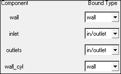
the Boundary selection subpanel are already added.
Set the correct Bound Type for each one of the selected components. You want to
generate a boundary layer from components wall and wall_cyl, therefore, you will
leave wall as their Bound Type. Also verify that the Bound Type of components
inlet and outlets is set to in/outlet as shown, following:
Figure 3.
A component with Bound Type: wall indicates that you are going to generate a
boundary layer mesh on the component later on when you generate the mesh.
Therefore, the same component should be consistently specified with the
comps selector for the With BL (fixed or float) in the Boundary selection
subpanel.
A component with a Bound Type: slip, symmetry, in/outlet, or farfield
indicates that you are NOT going to generate a boundary layer mesh on the
component. Therefore, when you generate the mesh this component should be
consistently specified with the comps selector for the W/o BL (fixed or
float) in the Boundary selection subpanel.
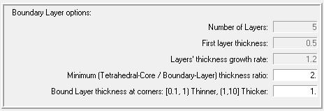
Specify the Boundary Layer options as shown in the following image.
Figure 4.
The first three fields are set in the BL parameters subpanel and cannot be
changed here. All layers will have the same thickness except in area
affected by the distributed thickness "loading" and also mesh smoothing
operations such as hyperbolic smoothing at corners.
Specify a Minimum (Tetrahedral-Core / Boundary-Layer) thickness ratio value
of 2.0. This means that in areas where there is not enough room to grow the
nominal BL (5 layers starting with a thickness of 0.5 and increasing with a
grow rate of 1.2), the boundary layers’ thickness will be reduced so that
the tetrahedral core thickness is approximately at least 2.0 times the total
boundary layer thickness, except for mesh smoothing operations such as
hyperbolic smoothing at corners and convex/concave areas.
The last option, Bound Layer thickness at corners, is a coefficient that
controls the hyperbolic growth where walls make an angle. The smaller this
value is, the thinner the total BL thickness is in such areas; values less
than 1 produce thinner layers and values greater than 1 produce thicker
layers.
Now you are ready to generate the Distributed BL Thickness loading. Make sure
that none of the elements specified in the boundary collectors are masked.
If they are masked an error message will indicate that there is a
discrepancy between the total number of elements in the components that you
specified and the number of tria3/quad4 elements found (displayed). If you
have masked elements, you can use mask (F5), and
press unmask all.
Click Generate Distributed BL Thickness Ratio.
If the model already contains boundary layer thickness ratios, then a pop-up
message box will ask you if you want to keep such loads or if you want to
clear/discard them. Most of the time you will want to clear the existing
boundary layer thickness ratios; click Yes. In some
special cases you may want to keep them, if more than one loading value is
specified for a node, the minimum value is used when generating the
mesh.
After a few seconds you will see a pop-up message indicating the
number of distributed boundary layer thickness values included in collector
^CFD_BL_Thickness.
Click Close in the Generate Boundary Layer
distributed thickness values dialog.
Generate the Boundary Layer and Tetrahedral Core Mesh
In the CFD Tetramesh panel, click the Tetramesh
parameters subpanel.
Set the switch for the tetrahedral mesh generation algorithm to
Optimize Mesh Quality.
Ensure that the tetrahedral grow rate is switched to
Interpolate.
Click mesh to generate the mesh.
If collectors CFD_bl001 and CFD_tetcore001 are present, you will be asked if
you want to delete the elements in those collectors. Almost always you select
Yes. When this task is finished two collectors are created: CFD_bl001 and
CFD_tetcore001.
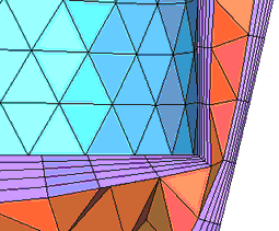
Mask Elements to Inspect the Boundary Layers’ Thickness on Thinner Areas
Click the icon.
Open the Mask panel by using the shortcut key F5.
Select elements to be masked by pressing Shift and the left mouse button, then move the cursor so that the
rubber band covers the upper half of the model.
Click mask.
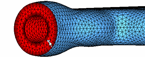
Click the icon.
Zoom in into the area where the bounding surfaces come close together. The
following image illustrates how BL interference has been avoided by reducing the
BL thickness.
Click return to close the Mask panel.
Figure 5. Figure 6.
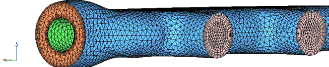
Arrange Volume and Surface Components Before Exporting the Mesh for CFD Solvers
First you need to put in the same component all the elements that represent a single
fluid and/or solid domain. In this case you have a single fluid domain, therefore
you proceed as follows:
Rename the CFD_Tetramesh_core component. Typically, select a name
“fluid*,” for example, fluid. In the Model Browser, select CFD_tetcore001,
right-click, select Rename, and then type the new name,
fluid.
Click BCs > Organize.
Click elems > by collector and select the collector CFD_bl001.
In the dest component field, select fluid.
Click move and then click
return.
Now you have all the volume elements in component fluid. The surface mesh of
this component is typically different from the surface mesh that was used to
define the boundary of the domain. For this reason, and to have consistent
surface zones to impose boundary conditions in most CFD solvers, you are going
to create new boundary components that will be used when exporting the mesh for
the CFD solver of your choice. To accomplish this you first extract the surface
mesh of component fluid. You do this by generating the surface elements.
Click BCs > Faces.
Select the component fluid, and click find
faces.
All boundary faces are placed in the component ^faces.
Create new, empty components to place the elements from ^faces so that when
these components are later exported, they can be used to set a boundary
condition in your CFD solver. In the Model Browser,
right-click Component, and then select
Create.
The Entity Editor opens.
For Name enter wall_exterior. Leave the Type as None.
Create three more empty components with the names wall_cylinder, inlet_annulus
and outlets3.
Move the elements from component ^faces into the newly created components. This
is done for clarity; however, most of the time you create one fewer component
and you rename ^faces which retains the remaining elements after you move
elements to the newly created surface components. Organize the components by
using the Organize panel. Click BCs > Organize.
Set dest component to wall_exterior, then pick one
element on the exterior wall surface in the ^faces component.
Click the elems switch and select by
face.
This will recursively select all the elements attached to the picked element
as long as the adjacent elements are within a break angle less or equal to the
value specified in the feature angle field (Preferences > Geometry Options >
Mesh subpanel). The surface mesh in ^faces is such that the zones that you want
to organize/move make an angle close to 90 degrees and their boundaries,
therefore this is a very easy job to do with a default feature angle of 20 or 30
degrees. Figure 7.
Having selected all the elements that should go to component wall_exterior,
click move.
Now set the dest component to outlets3 and pick at least
one element on each one of the three separate outlets.
Figure 8.
Click the elems switch and select by
face.
Having the elements on the three outlets selected, press
move.
Those elements are moved to component outlets3.
Set dest component to inlet_annulus and pick one
element.
Figure 9.
Right-click the elems switch and select by
face.
Having all the elements on the inlet annulus selected, press
move.
Those elements are moved to component inlet_annulus. Now that all the
remaining elements in component ^faces are the elements that you want to move to
component wall_cylinder.
Set dest component to wall_cylinder.
Click elems in the panel area
and select by collector.
Select the component ^faces.
Click move and then click
return.
The elements are moved to component wall_cylinder. Figure 10.
As mentioned previously, more often than not it is easier to
rename/recolor component ^faces.
Export the Mesh
Verify that only the components that you want to export are displayed. All
other components should not be displayed.
Click the icon to
open the Export tab.
Select the CFD file format of your choice to export the grid or mesh.
Summary
Engineering Solutions allowed you to generate
high-quality boundary layer meshes on parts where the clearance or separation of the
bounding surfaces is not enough to accommodate the user specified nominal boundary layer
thickness.
To accomplish this you first used the CFD utility Generate Distributed BL Thickness
Ratio to generate load collector ^CFD_BL_Thickness. This load collector is then used
when you enable distributed thickness. As shown in the cross-sectional images, the
mesh is very smooth, free of collisions, and is of excellent quality.
 , on
the Standard toolbar.
, on
the Standard toolbar.
 icon.
icon.
 icon.
icon.
 icon.
icon.
 icon to
open the Export tab.
icon to
open the Export tab.