Fix gaps between stitched edges and vertices to make the actual geometry of the
surfaces consistent with the model topology.
From the menu bar, click Geometry > Geom Match Topology.
The Geom Match Topology dialog opens.
Using the Entities selector, select geometry to
check.
In the Tolerance field, enter a tolerance to use when
checking the topology of the model for gaps between shared, non-manifold, or
suppressed edges.
If a gap is found to be bigger than the specified tolerance, then the surface
and edge geometries will be morphed parametrically and in 3D, if necessary,
to make the gap smaller than the tolerance. In addition, non-essential
degenerate edges are removed.
Click Apply.
The original geometric entity IDs are also preserved. The same functionality is used
for the Optimize for CAD option in the Export - Geometry Browser.
Example: Match Topology
This example demonstrates the difference in results when using the Geom Match
Topology tool to update geometry that has previously been repaired with
topology-based geometry cleanup operations, for example, toggle/equivalence/replace
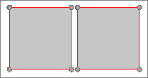
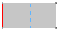
edges, replace points, and so on. Figure 1. Unrepaired Geometry
The geometry below was repaired using only topology-based geometry cleanup
operations. After the geometry was meshed, you can see that some of the elements
have become distorted. After untoggling the edges, there is still a large gap in the
geometry.
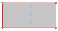
Figure 2. Repaired Geometry not Updated with the Geom Match Topology
Tool
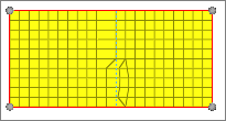
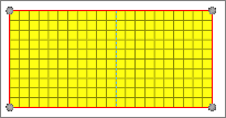
Figure 3. Meshed Geometry
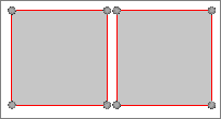
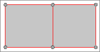
Figure 4. Geometry with Edges Untoggled
The geometry below was repaired using topology-based geometry cleanup operations and
then updated with the Geom Match Topology tool. After the geometry was meshed, you
can see that there are no distorted elements. After untoggling the edges, there is
not a gap in the geometry.
Figure 5. Repaired Geometry Updated with the Geom Match Topology
Tool