Seam Hexa Adhesives
The Seam Hexa Adhesives realization creates a continuous or discontinuous hexa weld with a predefined pattern.
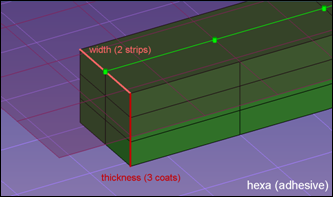
Figure 1. Seam Hexa Adhesives
Seam Hexas are created from the Seam panel.
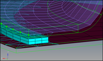
Figure 2.
For OptiStruct and Nastran solvers, the HEXA elements are tied to a shell using RBE3’s at locations where the HEXA nodes and shell nodes are non-coincident. If the HEXA nodes and shell nodes are coincident then RBE2's will be used to tie them.
For the LS-DYNA solver only, the shell gap thickness option is supported. If the HEXA nodes are coincident with shell nodes, then those shell nodes will be used to create HEXA elements. The HEXA elements at some or all nodes will be tied directly to the shells.
This realization type is intended to work on meshes, both shells and solids.
- The length of a hexa is predefined by the distribution of the test points along the seam connector. This is defined by spacing or density during the connector creation.
- The width of the single hexa depends on the number of strips and the defined total width of the seam, which is measured perpendicular to the seam direction.
- The thickness of a single hexa depends on the number of defined coats and the selected thickness option.
- shell gap
- The seam completely and exactly fills the gap between the two shells. Shell
thicknesses and offsets are not considered.
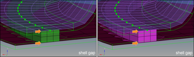
Figure 3. Shell Gap - maintain gap
- The seam is positioned in the exact middle between the shells. The seam thickness is
adjusted, that on both sides the gap between shell and seam fits the defined gap size.
Shell thicknesses and offsets are not considered.
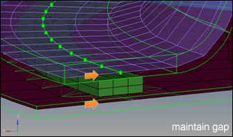
Figure 4. Maintain Gap - (t1+t2)/2
- The seam thickness is calculated by averaging both shell thicknesses. On the left
side the offsets and thicknesses are taken into account, so that the seam is
positioned around the middle of the air gap. On the right side the seam is just
positioned around the middle of the shell positions.
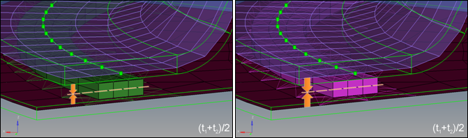
Figure 5. (t1+t2)/2 - midthickness
- On the left side the exact air gap is determined and filled with the seam. On the
right side the seam thickness is calculated by subtracting half the thickness of both
shells from the total distance of the shells.
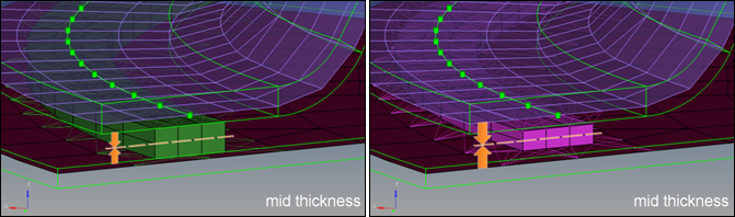
Figure 6. Midthickness - const. thickness
- The thickness of the seam is predefined for both; on the left side the seam is
positioned around the middle of the air gap, on the right side around the middle of
the two shells.
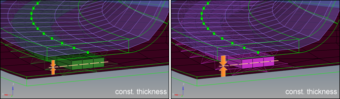
Figure 7. Const. Thickness