Line loads allow total loads (forces and moments) to be applied in a distributed
manner on nodes even though the load is applied on geometry lines or set of nodes forming
ordered edges.
Restriction: Only available in the Nastran
and OptiStruct solvers in the Aerospace user profile.
From the menu bar, click BCs > Create > Line loads or Aerospace > Loads/BCS > Line loads.
You can provide the total force or force/unit length. The program first calculates
the force per unit length from the total force and length of the lines (or total
node distances in case of node path). Then based on the nodal distance and the shape
functions of the elements, it distributes this 1D pressure (force/unit length)
evenly to the nodes within the element edge.
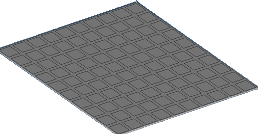
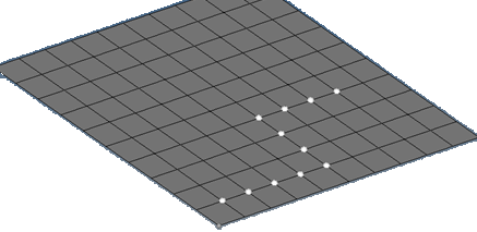
Select the geometry lines or the orderly picked node path. Figure 1. The List of Geometry Surface Edges/Lines can be Selected Figure 2. The list of Nodes can be Selected in an Ordered Sequence
The order of picking of the nodes or lines forms the edged used to calculate
the total length of the segments. Select the system on which the loads will
be applied (global or user defined).
Select the Load Distribution type.
Total Load: This total load will be uniformly distributed based on
uniform pressure to the element nodes based on the order of the
elements (liner or quadratic-mid nodes).
Load per unit length: You can directly provide the 1D element
pressure.
Constant load: This option takes the load you provide and applies it
to each node with the same magnitude entered in the dialog.
You can also select component magnitudes separately if you do not want to
use the vector option (Constant Vector - single magnitude or Constant
Components x,y,z values).
Enter the load magnitude depending on the load distribution type.
Select the Direction vector if the load type is
constant vector.
Indicate the force or moment.
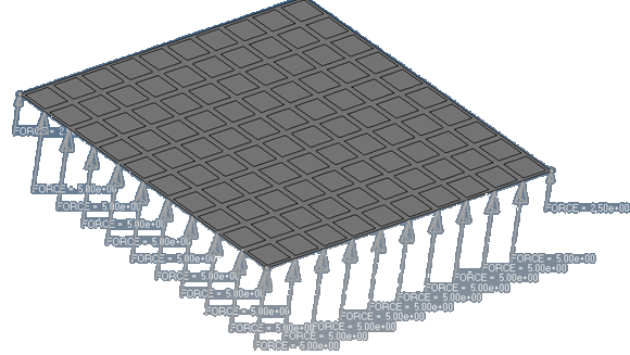
Click Apply. Figure 3. . Total load is distributed to nodal forces based on the element
edge length and order of the element. The summation of the loads
should match the total load applied.
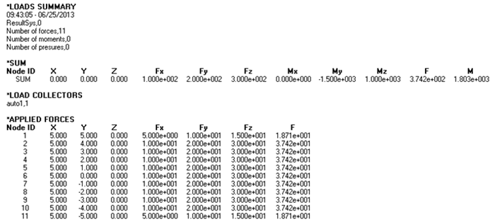
Load Verification
The total load will be distributed to each node based on the inter node distance. It
can be verified from the
menu bar by clicking BCs > Check > Loads Summation. Figure 4.
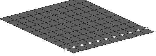
Total Load on a Node by Path
The order of the node pick is stored and used to calculate the path length, therefore
the picking order is important. Figure 5.