Auto E-Line Creation Tutorial
This section of the document will walk you through the Auto E-Line Creation steps.
For the tutorial purpose, you will create E-Line connector locations for between the
following components:
Control Panel UpperandIP SubstrateDashboard PanelandIP Substrate
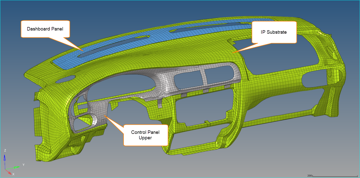
Figure 1.
Auto creation of connectors for Tutorial
-
Click
 Components button.
Component selection panel will activate.
Components button.
Component selection panel will activate.From graphics area, select
Control Panel UpperandIP Substrateand click proceed -
Click Geometric Lines
 button.
Line selection panel will activate.
button.
Line selection panel will activate.From graphics area, select the line present between the selected component and click proceed.
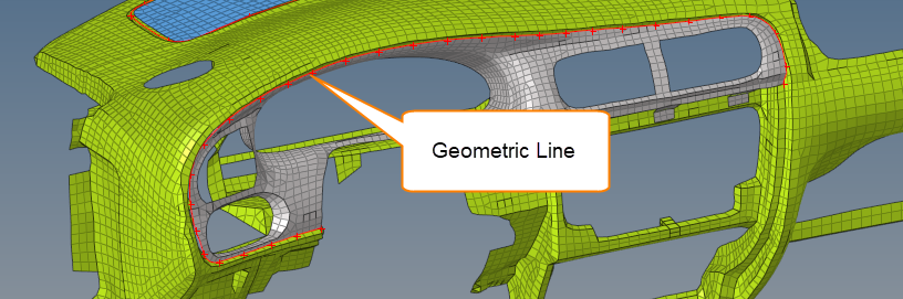
Figure 2. -
Keeping the other values default, click Create
 This should create the connector locations highlighted in
yellowas shown below.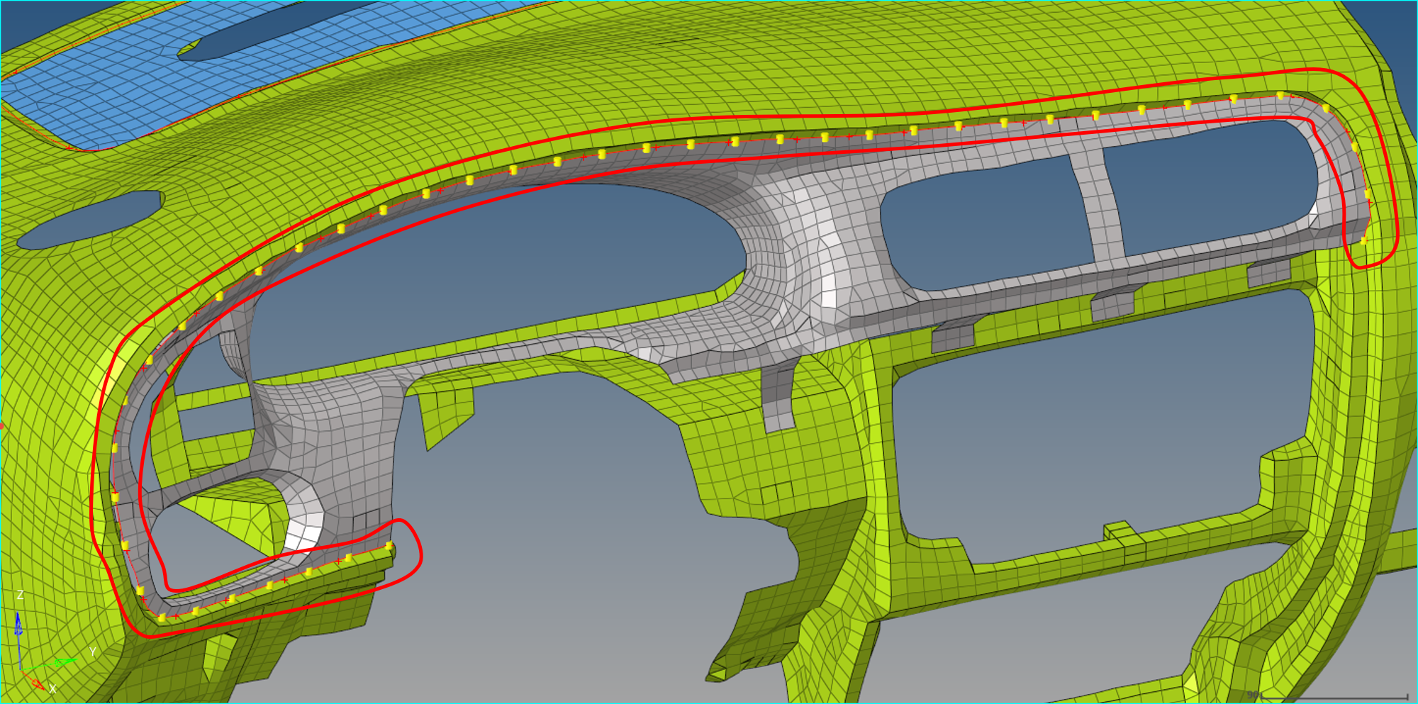
Figure 3. -
Similarly, repeat above steps to create a Squeak line
between
Dashboard PanelandIP Substrate.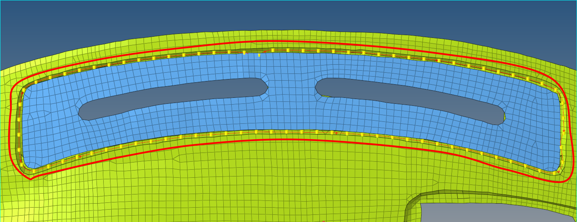
Figure 4.