Flux-AMESim co-simulation: 3-phase rotating motor
Conditions of operation
The studied device is a 3-phase rotating motor.
It is characterized by:
- the rotor of the motor - a mobile part in rotation around an axis
- the magnetic circuit of the motor where induced currents can develop (rotor bars)
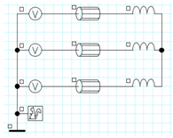
- the 3 stator winding, three-phase voltage supplied
Description in Flux
The described device in Flux should observe the rules listed in the table below.
- Dimension: 2D plan, 2D axi, Skew, 3D
- Application: Magnetic Transient
- Physical:
| Mechanical |
A mobile mechanical set with …
|
|
| Electrical |
Three coils supplied by three voltage sources…
|
|
- Solving: The scenario(s) of solving defined in Flux will not be taken into consideration. It is AMESim that manages the time step of the simulation and imposes it to Flux during the co – simulation.
- no more than one mechanical set
- exactly three coils
- exactly three voltage sources
Coupling component
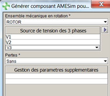
To carry out a Flux-AMESim co-simulation, the user creates in Flux a coupling component (phase 1).
The coupling component facilitates the:
- setting of the conditions for data exchange
- generation of the Flux project co-simulation (named F2A)
Conditions of exchange / 3-phase rotating induction motor:
- name of the mechanical set in rotation
- name of the three voltage sources (three phases)
- choice for the calculus of losses:
- without losses / with losses
- losses in the electrical circuit
- electromagnetic losses
- addition of supplementary parameters
The coupling component is created while the project is ready to be solved (physics completely described).
Exchange of data (1)
The exchange of data is done by means of the predefined parameters as shown in the diagram below.

Exchange of data (2)
The predefined I/O parameters in Flux (in conjunction with the coupling component creation) are presented in detail in the table below.
The input parameters in Flux are I/O parameters of multiphysical type. Their value is piloted by AMESim.
| I/O parameters of the multiphysical type | |
| AMESIM_PHASE1_VOLTAGE | Value of the voltage of phase 1 source voltage |
| AMESIM_PHASE2_VOLTAGE | Value of the voltage of phase 2 source voltage |
| AMESIM_PHASE3_VOLTAGE | Value of the voltage of phase 3 source voltage |
| AMESIM_ANGULARSPEED | Angular position of the mobile mechanical set |
| AMESIM_TEMPERATURE | Operating temperature |
The output parameters of Flux are I/O parameters defined by means of formulas.
| E/S parameter of the formula type | ||
| FLUX_PHASE1_CURRENT | Current in the phase 1 | I(NOM_SOURCE_TENSION_PHASE1) |
| FLUX_PHASE2_CURRENT | Current in the phase 2 | I(NOM_SOURCE_TENSION_PHASE2) |
| FLUX_PHASE3_CURRENT | Current in the phase 3 | I(NOM_SOURCE_TENSION_PHASE3) |
| FLUX_FORCE | Electromagnetic force over the mobile part | TorqueElecMag(NOM_EM_MOBILE) |
| FLUX_LOSSES | Losses in the electrical circuit, respectively the Joule losses in the stranded coils and in the resistors* of the electric circuit | FLUX_LOSSES_COND_BOB+FLUX_LOSSES_RESISTANCE |
| Electromagnetic losses, respectively the Joule losses in the regions of solid conductor type, due to the eddy currents | FLUX_LOSSES_DOMAIN | |