Mast Configuration (For Example, Quasi-Omni, Skew, Side Mounted)
The mast configuration allows the combination of multiple single antennas with a power splitter. So, for example, a homogeneous 360-degree coverage can be achieved (if all antennas are fed with the same signal and power).
With different settings in the power splitter or with non-equal angles between the antennas, the radiation can be concentrated into dedicated directions.
The example in Figure 1 shows a configuration with multiple antennas mounted around a mast. The number of antennas, as well as their azimuth and elevation (tilt), can be defined by you.
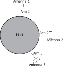
Figure 1. Example for quasi-omni configuration.
Figure 2 shows additional sub-arms at the end of one arm. Each antenna can be mounted additionally at such a sub-arm. The azimuth of this sub-arm can be defined arbitrarily, and it is independent of the azimuth of the main arm. So, two antennas with different azimuth orientation can be mounted at the same arm.
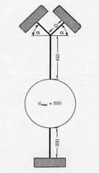
Figure 2. Example of quasi-omni with sub-arms.
The difference between quasi-omni, skew and side mounted is the value of the azimuth angle between antenna/sub-arm and arm. In skew the init value should be 90° (main radiation is tangential to the mast), while in quasi-omni as well as in side mounted the init value should be 0° (main radiation of antenna is orthogonal to the mast).
Quasi-omni and skew configurations allow multiple antennas at one mast while side mounted is limited to one antenna.
In MASC the azimuth angles between sub arms / antennas and arms can be defined individually, and the number of antennas can also be defined by the user. Therefore, you do not have to specify explicitly the configuration (quasi-omni, skew, side-mounted) to be used. Only the mast configuration must be selected. By defining the azimuth angles and the number of antennas, you select a configuration implicitly.
Therefore, all three configurations quasi-omni, skew and side mounted can be modeled with the mast configuration of MASC.
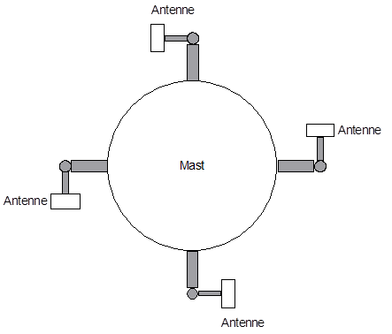
Figure 3. Example for skew configuration.
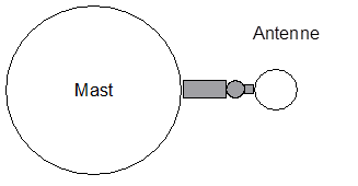
Figure 4. Example for side-mounted configuration.
- Number of (single) antennas considered: arbitrary (depends on RAM)
- Antenna
- Antenna type: directional (sector) antennas or omnidirectional antennas
- Pattern of the single antenna can be loaded from a file
- Mast
- Diameter of mast
- Height of mast
- Material of mast (reflection and transmission loss)
- Arms at mast
- Diameter and length of each arm as well as height where the arm is mounted at mast
- Material of arm (reflection and transmission loss)
- Azimuth of the arm [0°..360°]
- Azimuth of the antenna [0°.360°, relative to arm] (0° is equal to the direction of arm)
- Elevation (tilt) of antenna [-90°..90°]
- Radome
- Size and type (rectangular, circular) of the radome
- Material of radome (reflection and transmission loss)
- Electrical parameters
- Power splitter: relative split between antennas must be defined (for example, 1:1:2:1).
- Phase shifter: phase shift between antenna can be defined.
Side-mounted configurations are depending on the shadowing of the mast and arms and the reflections at the mast and arms. Depending on the distance between the antenna and mast, different radiation directions can be generated (see Figure 5).
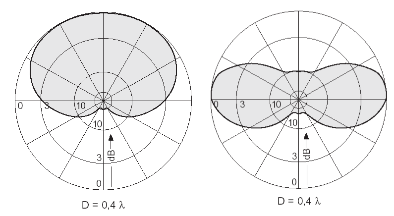
Figure 5. Examples of side-mounted configurations. Distance antenna-mast: lambda/4 (on the left) and distance antenna-mast: lambda/2 (to the right).
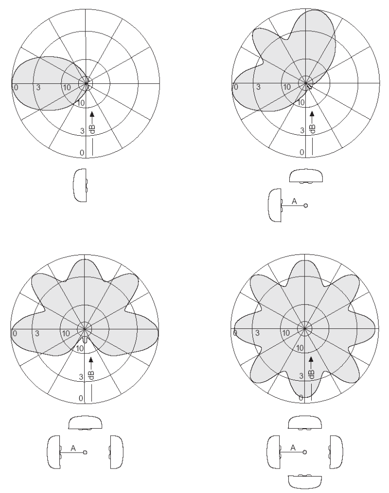
Figure 6. Examples of horizontal antenna patterns (quasi-omni configurations).