Munich, Germany
Calculate urban propagation in the city of Munich using the DPM.
Model Type
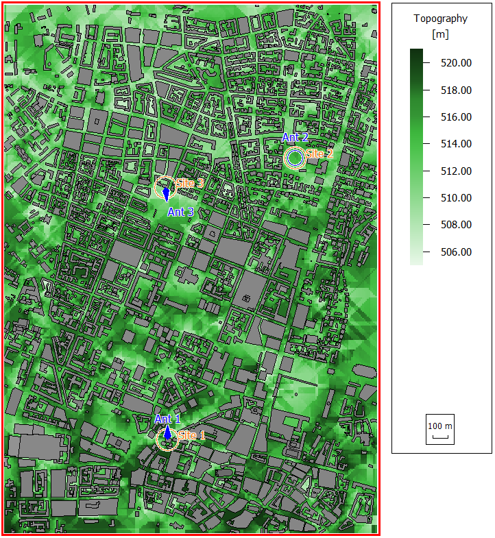
Figure 1. Topographical database with urban buildings for Munich.
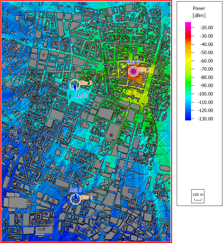
Figure 2. Power results for Site-2 Ant-2.
Sites and Antennas
There are three transmitter sites at different locations. Each site has a single antenna. One is an omnidirectional (isotropic) radiator operating on a carrier frequency of 900 MHz. The remaining two transmitters are directional antennas operating on a carrier frequency of 1800 MHz. The antenna patterns used in the scenario are stored in .apb files. The patterns can be visualized with AMan.
Computational Method
Results
Propagation results show at every location the power received from each transmitting antenna by a hypothetical isotropic receiver. Figure 2 shows power results for Site 2 Antenna 2 at a height of 1.5 m.