View Ray
This option allows the user to view the rays emitted by the source in the simulation.
This command plots the rays emitted by the source in the simulation.
When initially open, the panel will display the rays for a particular step, order and observation direction. All the effects type are selected by default. The user can change:
- Ray effect
- it is possible to select one of this options (direct, reflected, transmitted, creeping and diffracted) or all of them.
- Ray selection
-
- Order: the parametric step to select. These should have been defined prior to the calculation when designing the simulation.
- Radius: select a particular radius value.
- Theta: select a particular theta value.
- Phi: select a particular phi value.
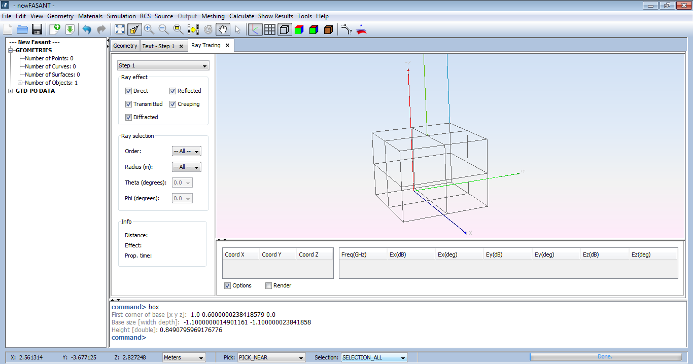
Figure 1. Ray visualization panel
The user can filter the rays that are displayed using the check boxes on the left panel. The user can also visualize the rays having a specific order.
After selecting a ray it will be highlighted in yellow color and its information will be shown in the panel at the bottom. The table on the left shows the coordinates of the points (source point, first reflection/diffraction point, second reflection/diffraction point... and the observation point). The table on the right shows the amplitude and phase for each of the field components. The values of the first line correspond to the vertical source polarization and the values of the second line correspond to the horizontal source polarization. However, if the source has been defined with a radiation pattern, this table will only have one line.
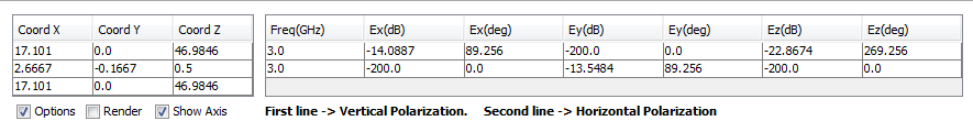
Figure 2. Ray visualization information