Pre-Processing
- What is the smallest fluid structure that I would like to resolve?
- What is the smallest solid geometry feature that I would like to resolve?
By resolving, it is implied to use a minimum of three to five particles across that fluid/solid structure. This by no means implies high accuracy, but a basic minimum of information that the result will provide. For analogy sake, ask yourself if you would consider the structure resolved if you used a finite-volume CFD code and had five cells across a structure. That is the approximate level of accuracy you can expect from having equal number of particles.
As in all CFD the more resolution, the better.
Protruding Shafts/Axles

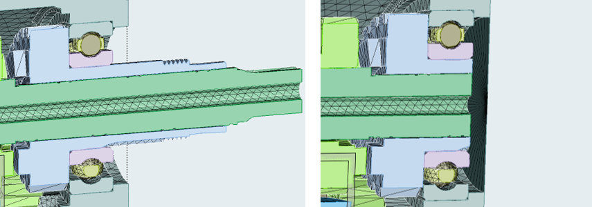
Figure 1. . Cross-section view of the shaft protruding outside of the gearbox housing (left) and the correctly shortened shaft with closed housing (right). The gap between the shaft and the housing will allow SimLab to recognize the volume without confusion. The gap between the wetted surface and the shaft is recommended to be on the order of the particle resolution.
Bearings
- Bearings are fairly large and there are only a handful of rolling elements
- Best practice: Leave the bearings and the rolling elements as they are, no need for any simplification.
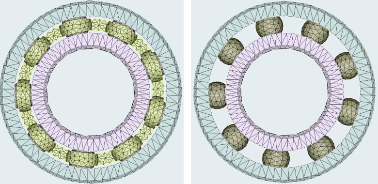
- Bearings are medium in size and have a considerable cage that holds the rolling elements (Figure 2)
- Best practice: Remove the cage. The remaining space will typically allow
for some flow through the bearing.

Figure 2. . Full bearing geometry, including the cage on the left. Simplified bearing geometry with removed cage on the right. With moderate resolution, typically several particles can pass between the rolling elements. - Many small rolling elements with or without the cage
- Best practice: Remove every other rolling element to create sufficient space in the bearing for the flow to go through. Remove the cage as well, if present.
- Option 1: keep the entire bearing static.
- Option 2: keep the outer ring static and move the rolling elements and the inner ring at the same RPM as the shaft/axle.
- Option 3: keep the outer ring static and move the rolling elements at half the RPM of the shaft/axle and the inner ring at the same RPM as the shaft/axle.
While technically Option 3 is the most accurate representation, it is also introducing several additional steps during the pre-processing (more motion definitions, introduction of another nanoFluidX phase). Given that completely accurate flow through bearings is typically beyond the reach of the most common nanoFluidX simulations Option 2 provides the best trade off between invested pre-processing time and accuracy of the solution.
Technically, it is possible to define the planetary motion of each individual rolling element, but without sufficiently high resolution (extreme resolution), such pre-processing detail would not bring much in terms of solution quality.
Overlapping Particles
Overlapping particles can occur during pre-processing because of machine precision and geometric properties of the discretized model.
SimLab does contain a command which analyzes the model and removes any overlapping particles.
Make use of this command. Following the workflow within SimLab (moving from left to right in the nanoFluidX toolbar), the overlap check and removal should be executed after particle creation.
It is generally suggested that solid (WALL and MOVINGWALL) particles remain preserved while the FLUID particles get removed. This is to ensure that sufficient solid particles remain in the walls, so no leaks would be caused by the removal of the overlapping particles.
For more instruction-based advice, consult the training material.