Impose Regions Definitions - Existing Syntax
nanoFluidX has the capability to define an arbitrary number of regions, which fall into one of the three categories (types): fluid velocity, body force, and temperature.
The fluid velocity region can be specified in a rectangular or spherical shape and it hard-imposes a velocity on all fluid particles which are within the prescribed region. The easiest analogy is a pump mechanism (momentum source), except that there are no moving parts involved. The body force region imposes a defined body force on all the particles which are within the defined region. It also can be thought of as a momentum source region, except that by defining the body force instead of hard-setting the velocity of the particles, the region is likely to behave more stably. Finally, the temperature region assigns a temperature to all fluid or wall particles (optional) which are within the prescribed region, and is essentially a heat source/sink.
imposeRegions
{
            imposeRegion
            {
                imposeRegion_type                  CUBOIDVEL
                cuboidvel_unv                      "1. 2. 0."
                cuboidvel_vel                      1.
                cuboidvel_min                      "0. 0. 0."
                cuboidvel_max                      "0.4 0.4 0.4"

                t_start                            0.
                t_end                              10.
                t_damping                          0.1

                cuboidvel_tvs_file                 time_velocity_series.txt
                cuboidvel_tvs_offset               0.1
                cuboidvel_tvs_latch                false

                imposeregion_motphs                1
            }
            imposeRegion
            {
                imposeRegion_type                   CYLINDERVEL
                cylindervel_unv                     "1. 2. 0."
                cylindervel_vel                     -0.4
                cylindervel_rad                     0.1
                cylindervel_pbl                     true

                ;[option 1]
                cylindervel_cntr                    "-0.4 0. 0."
                cylindervel_hght                    0.02
                ;[option 2]
                cylindervel_pnt1                    "-0.4 0. 0."
                cylindervel_pnt2                    "-0.4 0. 0."

                t_start                             0.
                t_end                               10.
                t_damping                           0.1

                cylindervel_tvs_file                time_velocity_series.txt
                cylindervel_tvs_offset              0.1
                cylindervel_tvs_latch               false

                imposeregion_motphs                 1
            }
            imposeRegion
            {
                imposeRegion_type                   SPHEREVEL
                spherevel_unv                       "1. 2. 0."
                spherevel_vel                       -1.
                spherevel_cntr                      "-0.4 0. 0."
                spherevel_rad                       0.02

                t_start                             0.
                t_end                               10.
                t_damping                           0.1

                spherevel_tvs_file                  time_velocity_series.txt
                spherevel_tvs_offset                0.1
                spherevel_tvs_latch                 false

                imposeregion_motphs                 1
            }
            imposeRegion
            {
                imposeRegion_type                   CUBOIDACC
                cuboidacc_acc                       "1. 0. 0."
                cuboidacc_min                       "0. 0. 0."
                cuboidacc_max                       "0.4 0.4 0.4"

                t_start                             0.
                t_end                               10.
                t_damping                           0.1

                imposeregion_motphs                 S1
            }
            imposeRegion
            {
                imposeRegion_type                   CUBOIDTEMP
                cuboidtemp_temp                     "1. 0. 0."
                cuboidtemp_fluidonly                false
                cuboidtemp_min                      "0. 0. 0."
                cuboidtemp_max                      "0.4 0.4 0.4"

                t_start                             0.
                t_end                               10.
                t_damping                           0.1

                imposeregion_motphs                 1
            }
            imposeRegion
            {
                imposeRegion_type                   CUBOIDPOROUS
                use_prtl_reuni                      false
                cuboidporous_min                    "0.0 0.0 0.0"
                cuboidporous_max                    "0.4 0.4 0.4"

                porous_inert                        "1000.0 10.0 1000.0"
                porous_visc                         "100.0  100.0 10.0"
                t_start                             0.0
                t_end                               10.0

                imposeregion_motphs                 1
            }
            imposeRegion
            {
                imposeRegion_type                   CYLINDERPOROUS
                use_prtl_reuni                      false
                cylinderporous_unv                  "1.0 1.0 1.0"
                cylinderporous_cntr                 "0.2 0.2 0.4"
                cylinderporous_hght                 0.8
                cylinderporous_pnt1                 "0.0 0.1 0.2"
                cylinderporous_pnt2                 "0.0 0.1 0.4"
                cylinderporous_rad                  1.0

                porous_inert                        "1000.0 10.0 1000.0"
                porous_visc                         "100.0  100.0 10.0"
                t_start                             0.0
                t_end                               10.0

                imposeregion_motphs                 1
            }
            imposeRegion
            {
                imposeRegion_type                   SPHEREPOROUS
                use_prtl_reuni                      false
                sphereporous_cntr                   "-0.4 0.0 0.0"
                sphereporous_rad                    25.0e-2

                porous_inert                        "1000.0 10.0 1000.0"
                porous_visc                         "100.0  100.0 10.0"
                t_start                             0.0
                t_end                               10.0

                imposeregion_motphs                 1
            }
            ...
}- t_start / t_end
- Common parameters for all imposed regions, indicating beginning and end of time at which the region is active.
- t_damping
- During this period, the prescribed velocity, body force or temperature will reach it prescribed value (analogous to the t_damping in the Imposed Motions section).
- imposeregion_motphs
- Impose regions are capable of following a MOVINGWALL phase with a predefined motion.
- imposeRegion_type
- Defines the type of the imposed region.
- cylindervel_unv, cuboidvel_unv, spherevel_unv
- Defines the velocity normal vector within an imposed velocity region. This determines the direction of the velocity vector.
- cylindervel_vel, cuboidvel_vel, spherevel_vel
- Defines the velocity magnitude within an imposed velocity region.
- cuboidvel_min, cuboidacc_min, cuboidtemp_min, cuboidporous_min
- Minimum bounds of the rectangular impose region box.
- cuboidvel_max, cuboidacc_max, cuboidtemp_max, cuboidporous_max
- Maximum bounds of the rectangular impose region box.
- cylindervel_rad, cylinderporous_rad
- Cylinder radius.
- cylindervel_pbl
- Boolean switch that enables a parabolic velocity profile when cylindrical imposed velocity regions are used.
- Use a direction vector, starting point, and cylinder height to define a cylinder.
- Use two points, where point 1 is the starting point and point 2 is the ending point (thus defining the direction of the cylinder).
- cylindervel_cntr, cylinderporous_cntr
- Coordinates of the base point of the cylinder.
- cylindervel_hght, cylinderporous_hght
- Height of the cylinder (distance between two bases).
- cylindervel_pnt1, cylinderporous_pnt1
- Coordinates of the base point of the cylinder.
- cylindervel_pnt2, cylinderporous_pnt2
- Coordinates of the top point of the cylinder.
- spherevel_cntr, sphereporous_cntr
- Location of the spherical velocity impose region.
- spherevel_rad, sphereporous_rad
- Radius of the spherical velocity impose region.
- cuboidtemp_temp
- Temperature which will be assigned to all the particles which enter the rectangular temperature region.
- cuboidtemp_fluidonly
- Switch which allows to prescribe the temperature to only fluids, or alternatively to all FLUID, MOVINGWALL or WALL particles.
- cuboidvel_tvs_file, cylindervel_tvs_file, spherevel_tvs_file
- Variable prescribed velocity file (Time Velocity Series – TVS).
- cuboidvel_tvs_offset, cylindervel_tvs_ offset, spherevel_tvs_ offset
- Time offset value in case that the TVS file starts at a time different from zero, for example begin using TVS at t = 10 s.
- cuboidvel_tvs_latch, cylindervel_tvs_latch, spherevel_tvs_latch
- Boolean command for keeping the last value of the TVS file throughout the simulation.
- use_prtl_reuni
- This command toggles the use of transport velocity or artificial particle displacement (APD) inside the porous region. It is considered to be an advanced parameter.
- porous_inert
- This command defines the inertial component coefficient in the Darcy-Forchheimer porosity model. If the values of this vector are all set to 0.0 and all the components of porous_visc are set to non-zero, then the used porosity model effectively becomes the Darcy model/equation.
- porous_visc
- This command defines the inertial component coefficient in the Darcy-Forchheimer porosity model. If only the values of this vector are used and all the components of porous_inert are set to 0.0, then the used porosity model effectively becomes the Darcy model/equation.
Impose Regions Definitions - New Syntax
nanoFluidX has the capability to define an arbitrary number of regions which can alter/prescribe velocity, acceleration, porous media or temperature.
There are two key categories which need defining: geometric shape and effect type.
Available geometric shapes are:
- PARALLELEPIPED
- CYLINDER (with or without hemispherical caps)
Available effect types are:
- Velocity (corresponding command suffix:
*vel) - Acceleration (corresponding command suffix:
*acc) - Porous media (corresponding command suffix:
*porous) - Temperature (corresponding command suffix:
*temp)
Any combination of shapes and effects is permitted, making for total of eight possible scenarios (or 12 if you count cylinders with hemispherical caps as a separate shape). The impose region type name is composed by specifying the geometric shape and adding the effect suffix in capital latters, for example: PARALLELEPIPEDVEL, PARALLELEPIPEDPOROUS, CYLINDERACC, or CYLINDERTEMP.
The fluid velocity region imposes a velocity on all fluid particles which are within the prescribed region. The easiest analogy is a pump mechanism (momentum source), except that there are no moving parts involved. The acceleration region imposes a defined acceleration on all the particles which are within the defined region. It also can be thought of as a momentum source region, except that by defining the acceleration instead of hard-setting the velocity of the particles, the region is likely to behave more stably. Porous media definition follows the well known Darcy-Forchheimer model and allows for defintion of volume averaged isotropic or non-isotropic porous media. Finally, the temperature region assigns a temperature to all fluid or wall particles (optional) which are within the prescribed region, and is essentially a heat source/sink.In addition to shape and effect types, there are specific commands which are applicable to a specific subset of desired shape-effect combinations. For example, as already mentioned, cylinder shape has a possibility to include hemispherical caps at the ends of the cylinder, such that if you specify the height of the cylinder as zero, you would end up with a spherical shape. More obviously, parameters which define the geometry are different between PARALLELEPIPED and CYLINDER impose regions.
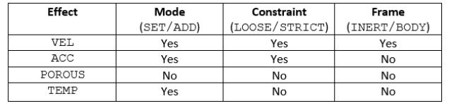
There is also a possibility to SET a magnitude of a desired field value inside the impose region or use the ADD the command to literally add the specified value to whatever instantaneous field value the particle might have inside the impose region.
One other variable which allows flexibility is the LOOSE/STRICT option, which allows for either hard (strict) imposing of the specified value, or soft (loose) imposing of the specified value. If we take an example of specifying velocity in X direction - STRICT definition will impose exactly the vector which the user provides, with Y and Z components being equal to zero. If we use the LOOSE option, the code will impose the X direction velocity, but will allow the solver to naturally accommodate (calculate) Y and Z velocity components.
Final option which is available is to define inertial (INERT) or body (BODY) frame of reference for velocity effect regions. If INERT is selected, the velocity definition in the region assumes that the general (default) simulation coordinate system is used, which is the common case. This means that whatever velocity is specified, it will be used as such. In case the user specifies the velocity and enables BODY frame of reference, the resulting velocity vector in the region will be specified vector plus the velocity of the body. This can be useful in specific scenarios.
The regions are defined through a separate parameter section called imposeRegions.
When specifying the geometry of the shape type commands in the imposeRegions, a specific nomenclature is followed. Each command begins with the shape definition, followed by a suffix which defines the effect, followed by an underscore and key suffix (which is effectively unique to each command). For example:
parallelepiped<effect>_A_vec or cylinder<effect>_axismore specifically resulting in parallelepipedvel_A_vec or cylinderporous_axis.
On the other hand, effect definitions are universal, such that once the impose region shape parameters are defined (using appropriate suffixes), you can add effect parameters.
We are emphasizing these definition principles in order to concisely (modularly) present the set of commands, instead of listing all eight (optionally 12) possible versions of the impose region definitions.
imposeRegions
{
imposeRegion
{
;NOTE:
;<shape> = {parallelepiped, cylinder}
;<effect> = {vel, acc, porous, temp}
; UNIVERSAL PARAMETERS
imposeRegion_type PARALLELEPIPEDTEMP
t_start 0.0
t_damping 0.1
t_end 20.0
imposeregion_motphs 1
<shape><effect>_mode SET
<shape><effect>_constraint LOOSE
<shape><effect>_frame BODY
<shape><effect>_tts_file time-temperature-series.txt
<shape><effect>_tts_offset 0.1
<shape><effect>_tts_latch false
; PARALLELEPIPED PARAMETERS
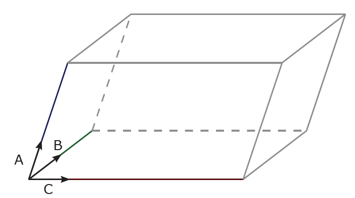
parallelepiped<effect>_corner "0.0 0.0 0.0"
parallelepiped<effect>_A_vec "1.0 0.0 0.0"
parallelepiped<effect>_A_len 2
parallelepiped<effect>_B_vec "0.0 1.0 1.0"
parallelepiped<effect>_B_len 4
parallelepiped<effect>_C_vec "1.0 0.0 1.0"
parallelepiped<effect>_C_len 3
; CYLINDER PARAMETERS
cylinder<effect>_axis "0.2 0.2 0.4"
cylinder<effect>_cntr "0.2 0.2 0.4"
cylinder<effect>_hght 0.8
cylinder<effect>_rad 1.0
cylinder<effect>_caps false
; VELOCITY PARAMETERS
<shape>vel_unv "1.0 2.0 0.0"
<shape>vel_vel 12.0
use_prtl_reuni false
; ACCELERATION PARAMETERS
<shape>acc_acc 100
<shape>acc_unv "0.0 0.0 1.0"
; TEMPERATURE PARAMETERS
<shape>temp_temp 150.0
<shape>temp_fluidonly false
; POROUS MEDIA PARAMETERS
porous_principal_ax_x "1.0 0.0 0.0"
porous_principal_ax_y "0.0 1.0 0.0"
porous_principal_ax_z "0.0 0.0 1.0"
porous_inert "1000.0 10.0 1000.0"
porous_inert_offdiag "1000.0 10.0 1000.0"
porous_visc "100.0 100.0 10.0"
porous_visc_offdiag "100.0 100.0 10.0"
}
}General Commands
- imposeRegion_type
- Type of the impose region.
- t_start / t_end
- Common parameters for all imposed regions, indicating beginning and end of time at which the region is active.
- t_damping
- During this period, the prescribed velocity, body force or temperature will reach it prescribed value (analogous to the t_damping in the Imposed Motions section).
- imposeregion_motphs
- Impose regions are capable of following a MOVINGWALL phase with a predefined motion.
- <shape><effect>_mode
- Defines the mode of the impose region, are the specified values added or set inside the impose region.
- <shape><effect>_constraint
- Defines the constraint of the impose region, are the specified values strictly or loosely imposed in the region.
- <shape><effect>_frame
- Defines the relevant reference system when specifying a velocity impose region.
- <shape><effect>_tts_file
- Name of the text file containing time-variable pairs (column format, no header, space delimiter), thus defining variable behaviour of the desired field inside the impose region (Time Table Series – TTS).
- <shape><effect>_tts_offset
- Time offset value in case that the TTS file starts at a time different from zero, for example begin using TTS at t = 10 s.
- <shape><effect>_tts_latch
- Boolean command for keeping the last value of the TTS file throughout the simulation.
Parallelepiped Specific Commands
- parallelepiped<effect>_corner
- Coordinates of the defining the origin corner of the parallelepiped
- parallelepiped<effect>_A_vec
- Three components of the vector A, which is defining one side of the parallelepiped.
- parallelepiped<effect>_A_len
- Length of the side A (magnitude of the vector A).
- parallelepiped<effect>_B_vec
- Three components of the vector B, which is defining one side of the parallelepiped.
- parallelepiped<effect>_B_len
- Length of the side B (magnitude of the vector B).
- parallelepiped<effect>_C_vec
- Three components of the vector C, which is defining one side of the parallelepiped.
- parallelepiped<effect>_C_len
- Length of the side C (magnitude of the vector C).
Cylinder Specific Commands
- cylinder<effect>_axis
- This vector defines the main axis of the cylinder.
- cylinder<effect>_cntr
- These are the coordinates of the center of the cylinder base where axis is located.
- cylinder<effect>_hght
- This command defines the height of the cylinder in the direction of axis.
- cylinder<effect>_rad
- Cylinder radius.
- cylinder<effect>_caps
- Boolean switch which controls adding of hemispherical caps on the cylinder bases (resulting in a pill-shape geometry).
Velocity Region Specific Commands
- <shape>vel_unv
- This vector defines the direction of the velocity.
- <shape>vel_vel
- This command defines the magnitude of the velocity.
- use_prtl_reuni
- This command toggles the use of transport velocity or artificial particle displacement (APD) inside the porous region. It is considered to be an advanced parameter.
Acceleration Region Specific Commands
- <shape>acc_unv
- This vector defines the direction of the acceleration.
- <shape>acc_acc
- This command defines the magnitude of the acceleration.
Temperature Region Specific Commands
- <shape>temp_fluidonly
- Switch which allows to prescribe the temperature to only fluids, or alternatively to all FLUID, MOVINGWALL or WALL particles.
- <shape>temp_temp
- Temperature which will be assigned to all the particles which enter the temperature region.
Porous Region Specific Commands
It is generally assumed (default) that the principal axes of the porous region align with the base simulation X, Y, and Z coordinates (inertial reference frame). If that is not the case, a separate coordinate system can be defined and the values defining porosity will be considered in that new coordinate system. The commands which define the custom principal axes of the porous region are:
- porous_principal_ax_x
- This command defines the X principal axis of the custom coordinate system
- porous_principal_ax_y
- This command defines the Y principal axis of the custom coordinate system
- porous_principal_ax_z
- This command defines the Z principal axis of the custom coordinate system
There are four parameters which define the volume averaged porosity of the region:
- porous_inert
- This command defines the diagonal inertial coefficients in the Darcy-Forchheimer porosity model. If the values of this vector are all set to 0.0 and all the components of porous_visc are set to non-zero, then the used porosity model effectively becomes the Darcy model/equation.
- porous_inert_offdiag
- This command defines the off-diagonal inertial coefficients in the Darcy-Forchheimer porosity model.
- porous_visc
- This command defines the diagonal inertial component coefficient in the Darcy-Forchheimer porosity model.
- porous_visc_offdiag
- This command defines the off-diagonal inertial component coefficient in the Darcy-Forchheimer porosity model.