In this tutorial you will learn how to use the Load Export utility to bridge the gap
between Multi-Body Dynamics (MBD) analysis and Finite Element (FE) analysis in MotionSolve.
The utility allows you to bridge this gap by doing the following:
Identifying and summarizing all loads acting on one/multiple body(ies) for any
given time step(s) in a tabular format.
Identifying and transferring all the forces and moments for one component at any
given time step(s) to a Nastran input deck that
contains GRID, CORD, FORCE, and MOMENT cards
Using Load Export
To use this utility, specify the components in the MotionSolve model for which loads are to be processed. You can do this by doing one
of the following:
Use the MotionView interface.
Edit the MDL model fle to add force output requests on body(ies).
When performing the MS/ADAMS solver run
on the MotionView model, you will get a
metadata file (an ASCII file written out from MotionView that contains information about force
output on a body).
This file along with the solver output files
viz. MS (*.plt) or ADAMS (*.req) become the input files for this utility.
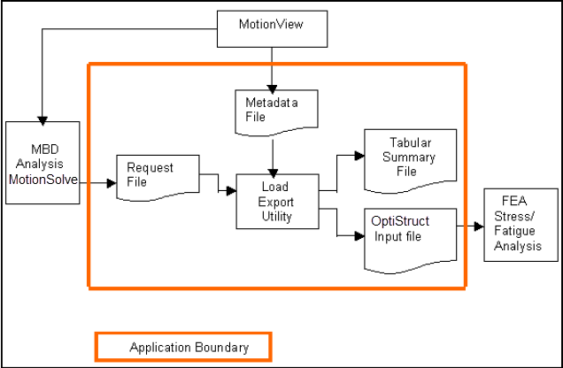
The application scope of this utility is shown in Figure 1: Figure 1. Interaction diagram
Create Metadata File and Launch Load Export
In this step you will create a metadata file and launch the Load Export
utility.
Before you begin, copy the
load_export.mdl file, located in the
mbd_modeling\externalcodes folder, to your
<working directory>.
Start a new MotionView session.
Load the front vehicle model file load_export.mdl, located
in <working directory>.
In the Project Browser, right-click on
Model and select Add > General MDL Entity > Output.
Tip: You can also add an Output if you right-click on the (Outputs) icon on the Model-General toolbar.
In the Add Outputs dialog, accept the default selections
and click OK.
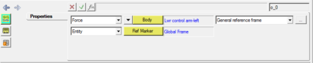
In the Output panel, use the drop-down menu to change the Output type from
Displacement to Force.
Double-click the collector.
In the Select a Body dialog, expand the folders Frnt macpherson susp > Bodies and choose Lwr control arm - left.
Tip: You can also select the Lwr control arm -
left directly from the modeling window by clicking the Body collector once.
Figure 2.
Repeat steps 3
through 7 to
create an output force request for Lwr control arm -
right.
Click the (Run) panel button.
From the Main tab in the panel, specify an End time of 2
seconds.
Save the solver input file as load_export.xml, to the
<working directory>.
Click the Run button to
invoke MotionSolve and solve the model.
MotionView creates a metadata file named
load_export.meta in the <working
directory>.
Use Load Export Utility and Generate Nastran Input Deck
In this step you will use the Load Export Utility and generate a Nastran Input Deck.
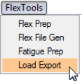
From the menu bar, click Flex Tools > Load Export.
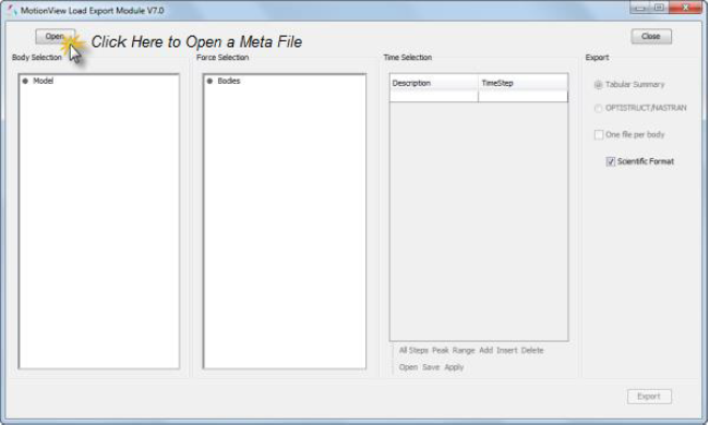
Figure 3. Launching the Load Export Utility Figure 4. The Load Export Utility
From the Load Export panel, open the file load_export.meta
from your <working directory>.
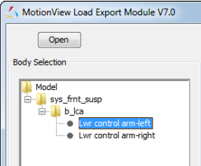
All bodies for which force outputs are requested are displayed in a tree
structure in the Body Selection panel. You can select one or multiple bodies
from the tree.
Expand the sys_frnt_susp folder and select the
Lwr control arm-left body.
Figure 5. Body Selection panel
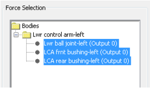
All the forces acting on the lwr control arm - left will display in the
Force Selection panel.
In the Force Selection panel, choose all three forces acting on Lwr
control arm - left.
Figure 6. Force Selection Panel
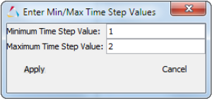
In the Time Selection panel, click the Range
button.
Specify a Minimum Time Step Value of 1 and a Maximum
Time Step Value of 2.
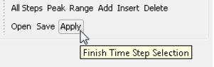
Figure 7. Activating the Export Panel
In the Time Selection panel, click Apply.
Figure 8.
Note: You must click the Apply
button to verify the validity of the time steps. If a time step you entered
is not present in the ADAMS request file, an
error message is generated and you must make corrections.
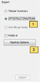
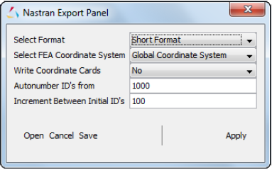
In the Export panel, click the OptiStruct/Nastran radio button.
Figure 9. Nastran options
Click the Nastran Options
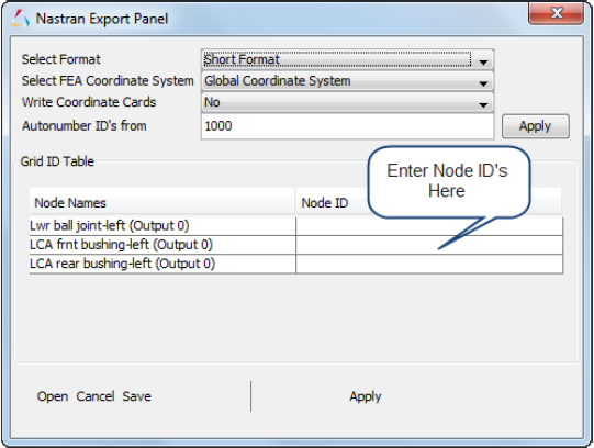
button to launch the Nastran Export Panel.
This dialog allows you to enter the Nastran node
ID numbers, as well as specifying the following options:
Nastran deck format (Large/Small)
The reference frame (LPRF/Global) in which the GRID cards are
written
Whether or not to explicitly output the CORD1R card in the input deck
(Yes/No)
Figure 10.
Accept the default selections in the dialog. Then specify the Node
ID's as follows:
Lwr ball joint - 1
LCA rear bush - 2
LCA frnt bush - 3
Click Apply.
On the Load Export panel, click Export.
Specify a file name and click Save.
This creates a subcase file, in addition to the Nastran input deck, in the same directory as the
.dat file.
Repeat steps 3
through 13 to
export loads on the Lwr control arm - right.
Note: If you select multiple bodies, the Nastran Export
Panel will look as show in Figure 11:
Figure 11. Nastran Export Panel for multiple body
selection
 (Outputs) icon on the Model-General toolbar.
 collector.
 (Run) panel button.