Post-processing: Generate Results for NLFE Components
You can post-process the NLFE components in your model in the same way you would a CMS flexible body.
There are three types of results available for the NLFE component.
Results in the MRF/ABF Output Files
The output MRF/ABF file contains the following signals for each grid of each NLFE component in your model:
| Y component | Description |
|---|---|
| DX, DY, DZ | Grid X, Y and Z positions. |
| UVX(1), UVX(2), UVX(3)
UVY(1), UVY(2), UVY(3) UVZ(1), UVZ(2), UVZ(3) |
X, Y and Z components of the gradient vectors in the X, Y and Z directions |
| VX, VY, VZ | Grid velocity in the X, Y and Z directions |
| WX, WY, WZ | Grid rotational velocity about the X, Y and Z axes |
Note, all of these are with respect to the global or ground frame, owing to the formulation of the ANCF.
Marker Based Results in the MRF/ABF/PLT
In addition to the above results, you may also use any marker based request on the NLFE component by attaching the marker to a grid on the NLFE component. For example, you may use expressions like DM(), VM() and any other marker based expression requests. These requests will be written out to all the output files including the MRF, ABF and the PLT.
Visualizing Stress, Strain and Displacement
For each NLFE component (composed of BEAM and/or CABLE elements) in your model, MotionSolve writes out a 3D representation in the H3D file. Using the H3D file in HyperView, you are able to visualize component stresses, strains and displacements in addition to animating the simulation. Figure 1 below illustrates this.
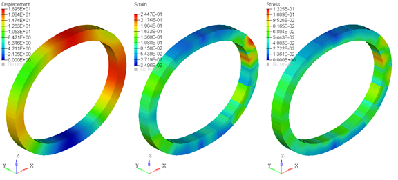
Figure 1. Displacement, Strain and Stress Contours
Note that the stresses/strains are calculated at the centroid of each element segment for both the BEAM and CABLE elements. The displacements, however, are calculated at all the nodes that are used to construct the three dimensional representation of the BEAM/CABLE. Owing to this difference and depending on the number of elements and segments in your NLFE component, the stress/strain contours may appear to be discontinuous while the displacement contours appear continuous when plotted in HyperView.
- Increase the number of NLFE sub-segments in your component. This leads to a finer discretization of the element shape and therefore the stresses are more accurate. Increasing the number of segments for your NLFE component will increase the post-processing time for your results. The solution time, however, should remain unaffected.
- Make use of stress averaging tools within HyperView. These are accessed in the Contour panel within HyperView. Using this method does not increase the post-processing or solution time in MotionSolve, since the averaging is done within HyperView with the available results in the animation H3D.
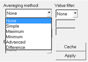
Figure 2. Contour Averaging Options in HyperView
Below is an example of plotting stress contours with and without stress averaging:
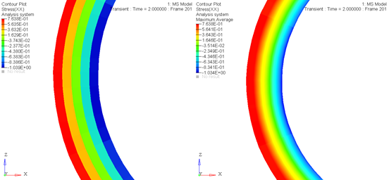
Figure 3. A stress contour of the same NLFE component with stress averaging OFF (left) and ON (right)
- Increase the number of elements in your NLFE component by defining more grid points. Although this is the most effective way to increase the accuracy of the stresses/strains, doing this also has the most severe effect on both the solution time and the time spent post-processing in MotionSolve. This option should only be used if the above two options do not give you satisfactory results. If you do increase the number of elements in your component to get more accurate stresses, you may consider doing so only in the areas of interest - for example, in curved sections of your component, or where stress concentrations are likely to occur.