HM-4310: Define Abaqus Contacts for 2D Models
In this tutorial you will define Abaqus contacts for 2D models.
- Load the Abaqus user profile and model
- Start Abaqus Contact Manager
- Define surfaces for 2D solid elements
- Define surfaces by set
- Define surface interaction property
- Define contact pair
This exercise uses the abaqus_contactManager_2D_tutorial.hm file, which can be found in <hm.zip>/interfaces/abaqus/. Copy the file(s) from this directory to your working directory.
Load the User Profile and Model
In this step you will load the Abaqus user profile and model.
A set of standard user profiles is included in the HyperMesh installation. While the user profiles change the appearance of some panels, they do not affect the internal behavior of each function.
-
Open a model file by clicking from the menu bar, or by clicking
 on
the Standard toolbar.
on
the Standard toolbar.
Start the Contact Browser
In this step you will start the contact browser.
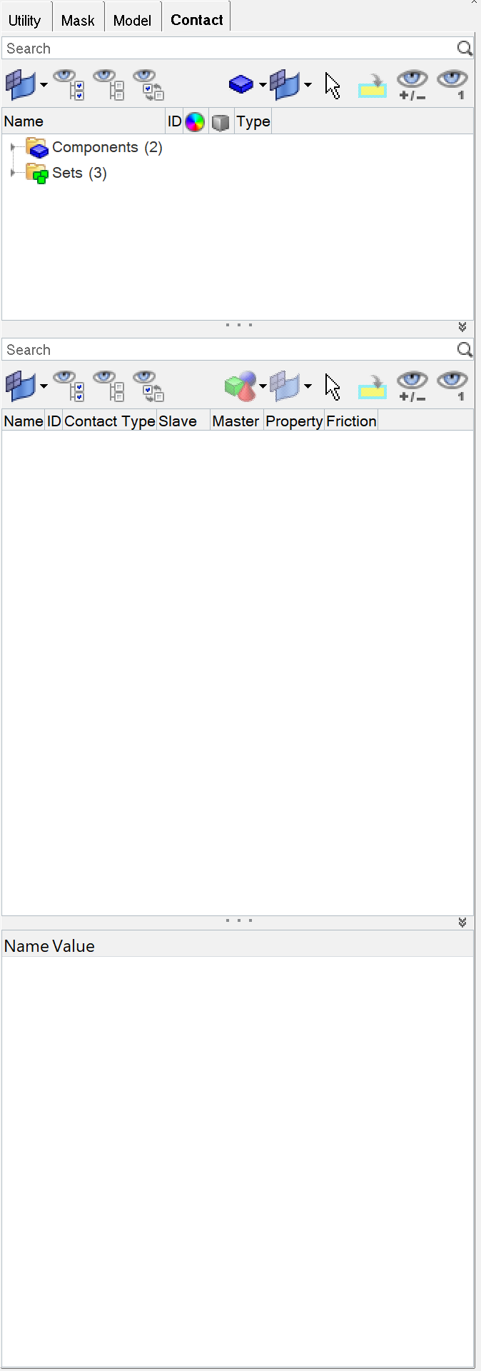
Figure 1.
Define Surfaces for 2D Solid Elements
In this step you will define surfaces for 2D solid elements.
In HyperMesh, you can define the *SURFACE, TYPE=ELEMENT card by using individual element IDs or sets with corresponding face identifiers.
-
Click the Define tab.
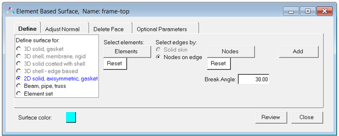
Figure 2. -
Click select.
The elements in the frame component highlight.
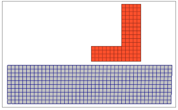
Figure 3. -
In the panel area, select two nodes from the top of a
selected solid element as shown in the image below.
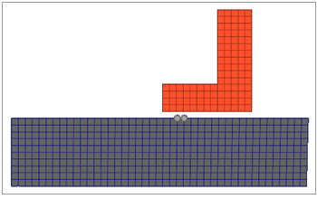
Figure 4. -
Click Add.
All of the edges of the selected solids that fall within the break angle of the edge defined by the two nodes are found.These edges are added to the current surface, and special contact surface elements are created to show the normal direction of those elements. In the current example, they show towards the component slider, which is correct.
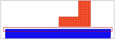
Figure 5. -
Click the Adjust Normal tab to change the normal
direction. The element normal should be adjusted towards the mating surface. The
element normal should be adjusted towards the mating surface.
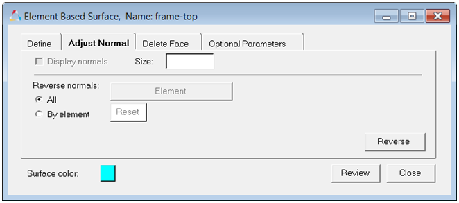
Figure 6. -
Click the Delete Face tab to delete the edges that you
do not want.
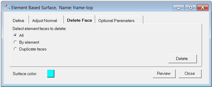
Figure 7.
Define Surfaces by Set
In this step you will create surfaces by defining a set and corresponding face identifiers.
In HyperMesh, you can define the *SURFACE, TYPE=ELEMENT card by using individual element IDs or sets with corresponding face identifiers.
-
Click Review Set.
All elements in the set highlight.
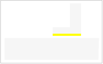
Figure 8. -
Click Update.
A new dataline for ELSET slider-bot has been added to the *SURFACE card. By selecting NoLabel the face identifier has been left blank.
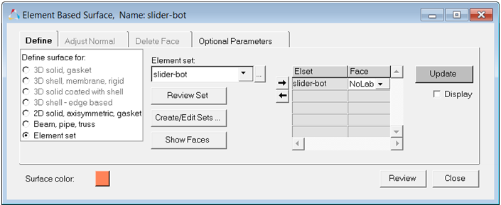
Figure 9. -
Click Review to review the contents of the *SURFACE
card. Right-click on Review to reset the
highlighting.

Figure 10. -
Select the Trimming of open free surface checkbox and
select YES.
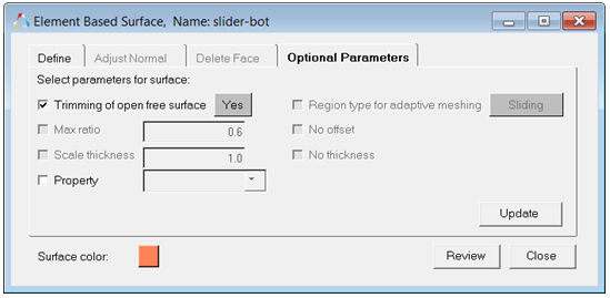
Figure 11. -
Click Display All to display all surfaces.
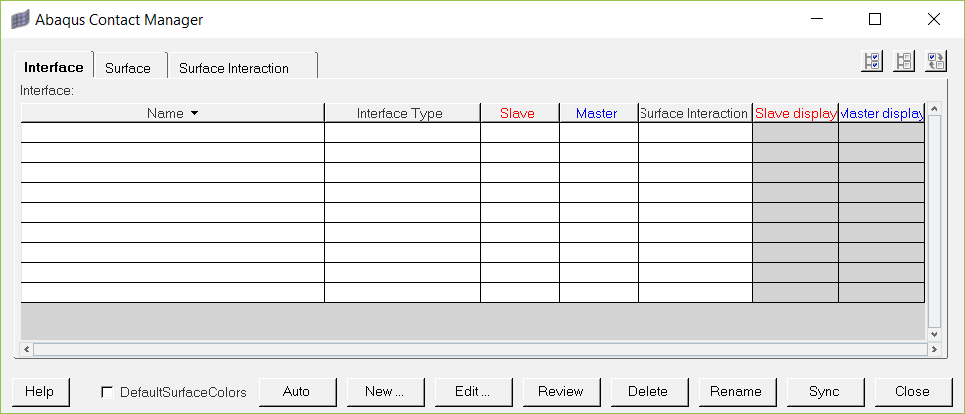
Figure 12.
Define the Surface Interaction Property
In this step you will define the *SURFACE INTERACTION card with the corresponding *FRICTION card.
-
Set Select mechanical interaction properties to
Friction.
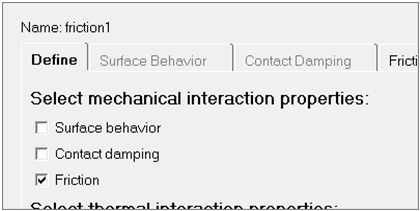
Figure 13. -
In the second pane, select Direct.
Note: Selecting this option means that the exponential decay and Anisotropic parameters will not be written to the input file.
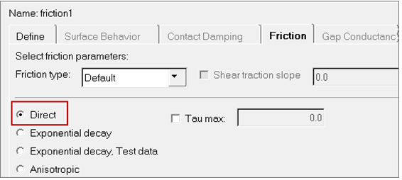
Figure 14. -
In the Friction Coeff column, click the first cell and type
0.05.
For Direct and Anisotropic tables:
- Change the number of columns in the table by specifying a value in the No of Dependencies field; change the number of rows in the table by specifying a value in the No of data lines field.
- Enter values in the table by clicking a cell to make it active and then typing in values. The table works like a regular spreadsheet.
- Read comma-delimited data from a text file by clicking Read From a File. In the File Browser, select a file and click Open to export the comma-delimited data. The row number will be set to the number of data lines found in the file.
- Access copy, cut, and paste options by right-click in the table. Comma-separated data can be copied/cut into or pasted from clipboard with these options. Relevant hot keys (for example, Ctrl-C, Ctrl-X and Ctrl-V in Windows) will also work.
- Activate cells by left-clicking in a cell. Clicking into an already active cell moves the insertion cursor to the character nearest the mouse.
- Highlight cells by left-clicking while moving the mouse over a cell.
- Move the active cell using the left, right, up, and down arrows.
- Extend the selection in a specific direction using Shift-<arrow>.
- Move the insertion cursor within a cell using Ctrl-left arrow and Ctrl–right arrow.
- Selects all cells using Ctrl-slash.
- Delete the character before the insertion cursor in the active cell using Backspace. If multiple cells are selected, Backspace deletes all selected cells.
- Remove the character after the insertion cursor in the active cell using Delete. If multiple cells are selected, Delete removes all selected cells.
- Move the insertion cursor to the beginning of the active cell using Ctrl-A. Move the insertion cursor to the end of the active cell using Ctrl-E.
- Decrease and increase the width of the column with the active cell in it using Ctrl-minus (-) and Ctrl-equal (=).
- Interactively resize a row or column by left-clicking or right-clicking on a border while moving the mouse.
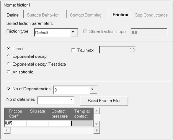
Figure 15.
Define the Contact Pair
In this step you will define the *CONTACT PAIR card with corresponding surfaces and surface interactions.
-
Repeat steps 7 and 8, selecting frame-top and clicking
Master>> to move it into the table as the master
surface.
Note: To more clearly see the surfaces available for selection, click
 . This
opens an enhanced browser where you can easily search for the appropriate
item. You can also click Filter to filter the items
displayed.
. This
opens an enhanced browser where you can easily search for the appropriate
item. You can also click Filter to filter the items
displayed.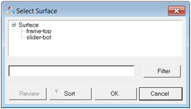
Figure 16. -
Set Interaction to friction1, which is the interaction
property for the current contact pair.
Note: To more clearly see the surfaces available for selection, click. This
opens an enhanced browser where you can easily search for the appropriate
item. You can also click Filter to filter the items
displayed.
-
Click OK to go back to the
Abaqus Contact Manager.
Figure 17. -
At this point, you have created the contact pairs required. Review any contact
pair by selecting it from the table and clicking Review.
The main surface is displayed in blue, the secondary surface is displayed in red,
and the rest of the model is shown in grey. If a surface is defined with sets
(display option disabled), the underlying elements are highlighted.
Right-clicking on Review will clear the
highlighting.
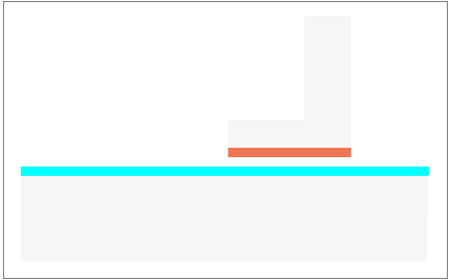
Figure 18.