HM-4320: Define Abaqus Contacts for 3D Models
In this tutorial you will define Abaqus contacts for 3D models.
- Load the Abaqus user profile and model
- Start the Abaqus Contact Manager
- Define surfaces for solid elements
- Define surfaces for shell elements
- Define surfaces by set
- Define surface interaction property
- Define contact pair
This exercise uses the contactManager_3D_tutorial.hm file, which can be found in <hm.zip>/interfaces/abaqus/. Copy the file(s) from this directory to your working directory.
Load the User Profile and Model
In this step you will load the user profile and model.
A set of standard user profiles is included in the HyperMesh installation. While the user profiles change the appearance of some panels, they do not affect the internal behavior of each function.
-
Open a model file by clicking from the menu bar, or by clicking
 on
the Standard toolbar.
on
the Standard toolbar.
-
In the Open Model dialog, open the
abaqus_contactManager_3D_tutorial.hm file.
The model appears in the graphics area.
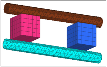
Figure 1.
Start the Contact Browser
In this step you will start the contact browser.
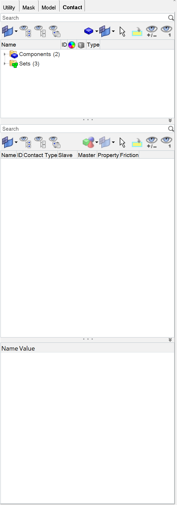
Figure 2.
Define Surfaces for Solid Elements
In this step you will define surfaces for solid elements.
In HyperMesh, you can define the *SURFACE, TYPE=ELEMENT card by using individual element IDs or sets with corresponding face identifiers. In this exercise, you will create surfaces by defining individual element IDs and corresponding faces.
-
On the Standard Views toolbar, click
 (XY Top Plane View).
-
Click select.
The elements in the BOX_1 component highlight.
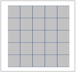
Figure 3. -
Click Add to add these faces to the current
surface.
HyperMesh creates special face elements (rectangles with a dot in the middle) for display.
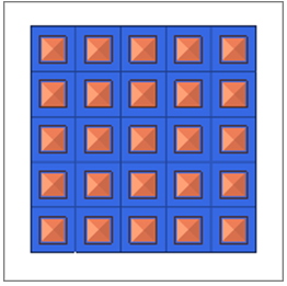
Figure 4.
Create the Box2-Top Surface
In this step you will create the box2-top surface.
-
On the Standard Views toolbar, click (XY Top Plane View).
-
Select two corner nodes (or three nodes) from the top of the selected solids as
shown below.
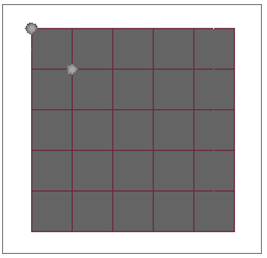
Figure 5. -
Click Add to find all faces of the selected solids that
fall within the break angle of the face defined by nodes.
HyperMesh adds these faces to the current surface and creates special face elements (rectangles with a dot in the middle) for display.
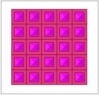
Figure 6.
Create the Cylinder-Top Surface
In this step you will create the cylinder-top surface.
-
Click Add to add these faces to the current
surface.
HyperMesh creates special face elements (rectangles with a dot at the middle) for display.
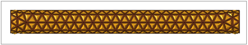
Figure 7.
Define Surfaces for Shell Elements
In this step you will create surfaces by defining individual element IDs and corresponding normals to define the SPOS/SNEG faces.
In HyperMesh, you can define the *SURFACE, TYPE=ELEMENT card by using individual shell element IDs or sets with corresponding SPOS/SNEG face identifiers.
-
The normals of the selected elements will be displayed at this point. If the
normals are too big, click
 (YZ Front Plane View) on the
Standard Views toolbar.
(YZ Front Plane View) on the
Standard Views toolbar.
-
Click Add to add these faces to the current
surface.
HyperMesh creates special face elements (rectangles with a dot at the middle) for display.
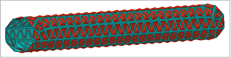
Figure 8. -
Click Display normals. Notice that all normals are
pointing outwards.
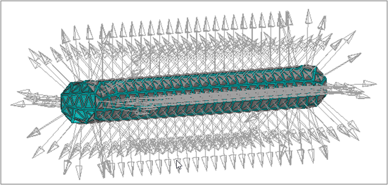
Figure 9.
Create the Box1-Bot Surface
In this step you will create surfaces by defining a set and corresponding face identifiers.
In HyperMesh, you can define the *SURFACE, TYPE=ELEMENT card by using individual element IDs or sets with corresponding face identifiers. HyperMesh allows only one set in a surface. It also does not support a combination of sets and individual elements in the same *SURFACE data line.
-
On the Standard Views toolbar, click
 (YX Bottom Plane
View).
(YX Bottom Plane
View).
-
Select the Display checkbox and then click
Update.
HyperMesh adds the selected set and face identifier to the current surface. In addition it creates a special display for the surface.By default, HyperMesh does not create a display for surfaces defined with sets. However, if you select the Display checkbox before clicking Update, it will create a special display using contact surface elements. The special display does not have any link to the set in the HyperMesh database. Therefore, if you edit the set later on, the display will not reflect them automatically. In this case, you need to come to this page, select the Display checkbox and click Update again.
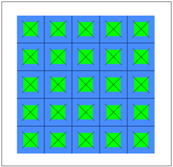
Figure 10.
Create the Box2-Bot Surface
In this step you will create the box2-bot surface.
-
On the Standard Views toolbar, click (YX Bottom Plane
View).
-
Click create.
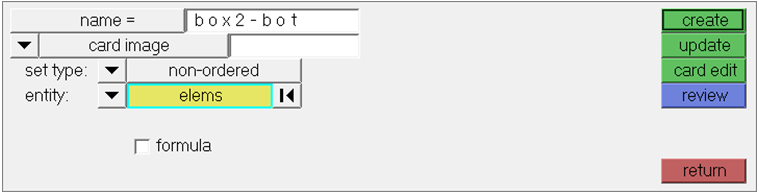
Figure 11. -
On the Standard View toolbar, click
 (Isometric).
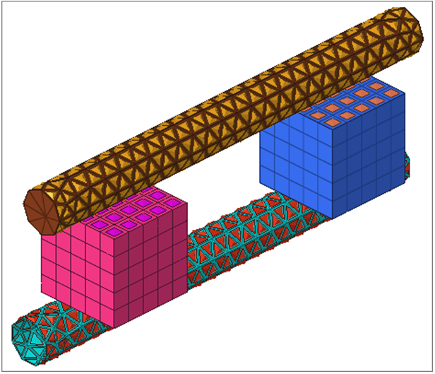
Figure 12.
Define the Surface Interaction Property
In this step you will define the *SURFACE INTERACTION card with a corresponding *FRICTION card.
Define the Contact Pairs
In this step you will define the *CONTACT PAIR card with corresponding surfaces and surface interaction.
-
Click Review.
The selected surface highlights red. If the surface is defined with sets (display option disabled), the underlying elements highlight. Right-click on Review to clear the highlighting.Clicking New opens the Create New Surface dialog, from which you can create a new surface. When you are done creating and defining the surface, the Contact Pair dialog returns with the new surface selected as the secondary surface.
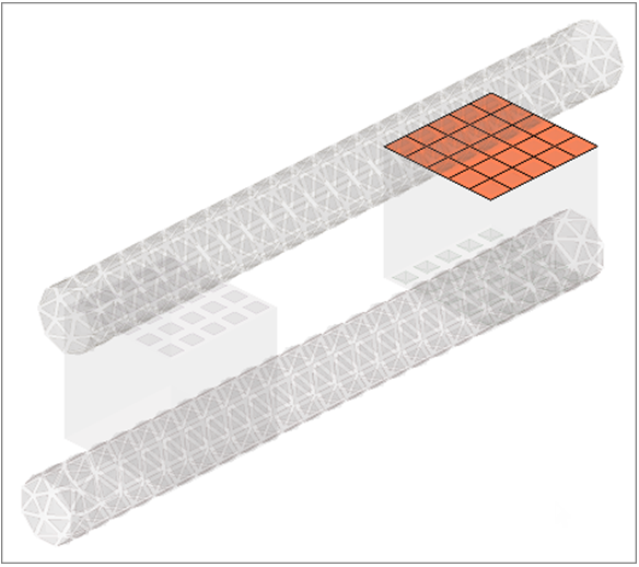
Figure 13. -
Repeat Steps 10.7 and 10.8, selecting cylinder-top and
clicking Master>> to identify it as the master
surface.
Note: To more clearly see the surfaces available for selection, click
 . This
opens an enhanced browser where you can easily search
for the appropriate item. You can also click Filter
to filter the items displayed.
. This
opens an enhanced browser where you can easily search
for the appropriate item. You can also click Filter
to filter the items displayed. -
Set Interaction to
friction1.
Note: To more clearly see the interactions available for selection, click. This
opens an enhanced browser where you can easily search
for the appropriate item. You can also click Filter
to filter the items displayed.
Create the Top-Cylinder-Box2 Contact Pair
In this step you will create the top-cylinder-box2 contact pair.
Create the Bot-Cylinder-Box1 Contact Pair
In this step you will create the bot-cylinder-box1 contact pair.
Create the Bot-Cylinder-Box2 Contact Pair
In this step you will create the bot-cylinder-box2 contact pair.
At this point, you have created all of the contact pairs required. Review any contact pair by selecting it from the table and clicking Review. Both the main and secondary surface highlight in red while the rest of the model is grey. If a surface is defined with sets (display option disabled), the underlying elements highlight. Right-click on Review to clear the highlighting.
Click Close to close the Abaqus Contact Manager.
- Click Edit to open the dialog for editing the selected interface, surface, or surface interaction.
- Click Delete to remove the selected interfaces, surfaces, or surface interactions. Multiple selections can be removed from the Interface table at once.
- Click Sync to update the Contact Manager with the current HyperMesh database. If you create, update, or delete any components, groups, properties, or entity sets from HyperMesh panels while the Contact Manager is open, click Sync to update the Contact Manager.
- If you minimize the Contact Manager dialog or if it goes behind HyperMesh, click to restore it.
- Bubble help exists for important buttons. Place the mouse on the buttons for a few moments to view it.
- Double-click on interface, surface, and surface interaction names in the table to open the corresponding edit dialog. Right-click on these names to display a pull down menu with options.
- Left-click or right-click on a table border while moving the mouse can resize columns in a table.
- Shift and Ctrl keys can be used while left-clicking to select multiple items in a table (useful for deleting multiple items).