Create Pretension Bolt
Create pretension loads in 1D and 3D bolts.
ANSYS: Create Pretension Bolt
Create pretension loads in 1D and 3D bolts of ANSYS models using the ANSYS PRETS179 element type.
-
Select source entities for the pretension bolt.
Option Description 1D pretension bolt - In the panel area, use the Nodes selector to select the nodes of the 1D elements where the pretension element needs to be created and then click proceed.
3D pretension bolt - In the panel area, use the Comps selector to select the
bolt component and then click proceed.Note: Multiple components are not allowed to be selected. If more than one bolt is selected, they will all be placed under one component.
- Use the elems selector to select the elements which form the cut section of the
bolt and then click proceed.Pretension elements are created at this section.
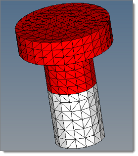
Figure 1. Example of a Typical Section - Use the node selector to select two or three nodes that define the load direction for the pretension load and then click proceed.
For 1D pretension bolts, PRETS179 elements are created at the node locations, with the pretension section created and associated to these elements. A SLOAD card with the given pretension load is also created.
For 3D pretension bolts, PRETS179 elements are created at the cut section with the pretension section created and associated to these elements. A SLOAD card with the given pretension load is also created.
Samcef: Create Pretension Bolt
Create and edit 1D and 3D pretension bolt loads and bolt sections.
Create a 1D Pretension Bolt
-
Click .
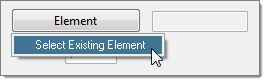
Figure 2. -
To automatically generate a pretension node at the second node of the selected
1D element, select the Auto generate pretension node
checkbox.
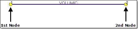
Figure 3.Once the 1D element is selected, the generated pretension node's ID is displayed in the Node ID field.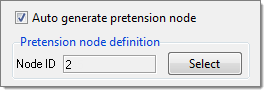
Figure 4. -
Click Load Collector and select where to store the
defined load.
- Choose Select Existing Collector to open the panel area where you can use the loadcol selector to select an existing load collector.
- Choose Create New Collector to create a new load collector with the prefix PRETENS_#. The number appended to the end of the load collector name depends on the number of load collectors currently present in the model.
The load collector is created along the 1D bolt.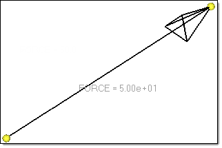
Figure 5.
A BOLT is created as a group entity.
The macro element ID for the first bolt that was created is written out as the maximum element ID in the model + the number of nodes present in model. 1000 is added to the macro element ID for consecutive bolts, that is, if the first bolt’s macro ID is 3, then the next bolt will be 1003 (3 + 1000).
The macro element ID of a bolt is reflected in its .SAI command, which is written along with the bolt’s corresponding output-code. It is preceded by the comment !!HM_TEMP_OUTPUTBLOCK, which enables the model-reader to ignore the output block upon import and not create any output blocks in HyperMesh. A bolt card that does not contain an output definition will not have a .SAI command written out.
All such commented commands are automatically exported out again upon re-export in the same format.
The load applied on a bolt is written out in the solver deck. A load’s magnitude is written out after VAL, and any curve attached to the load using Function Time is written after the keyword NF.
Create a 3D Pretension bolt
-
Click Contact Surface and select where to create a new
surface or select an existing surface.
- Choose Create New Surface to open the panel area where you can use the node list selector to
select two consecutive nodes to generate a contact surface. The first node
should be a base node in the desired contact surface. The second node should
lie in the direction of the contact surface's normal. A default name is
assigned to the new contact surface with the prefix PRETENS_#. The number
appended to the end of the name depends on the number of contact surfaces
currently present in the model.
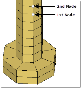
Figure 6. - Choose Select Existing Surface to open the panel area where you can use the contactsurf selector to select an existing contact surface.
- Choose Create New Surface to open the panel area where you can use the node list selector to
select two consecutive nodes to generate a contact surface. The first node
should be a base node in the desired contact surface. The second node should
lie in the direction of the contact surface's normal. A default name is
assigned to the new contact surface with the prefix PRETENS_#. The number
appended to the end of the name depends on the number of contact surfaces
currently present in the model.
A BOLT is created as a group entity.
The macro element ID of the first bolt that was created is written out as the maximum element ID in the model + the number of nodes present in model. 1000 is added to the macro element ID for consecutive bolts, that is, if the first bolt’s macro ID is 117653, then the next bolt will be 118653 (117653 + 1000).
The macro element ID of a bolt is reflected in its .SAI command, which is written along with the bolt’s corresponding output-code. It is preceded by the comment !!HM_TEMP_OUTPUTBLOCK, which enables the model-reader to ignore the output block upon import and not create any output blocks in HyperMesh. A bolt card that does not contain an output definition will not have a .SAI command written out.
All such commented commands are automatically exported out again upon re-export in the same format.
The load applied on a bolt is written out in the solver deck. A load’s magnitude is written out after VAL, and any curve attached to the load using Function Time is written after the keyword NF.