Manage Penetrations/Intersections
Check components or groups for element penetrations and intersections using the Penetration Check tool.
Penetration and intersection can be used individually or collectively. Penetration is defined as the overlap of the material thickness of shell elements, while intersection is defined as elements passing completely through one another.
-
Set up the Penetration Check and check for intersections/penetrations.
-
In the Penetrations browser, click
 to invoke the collision setup widget.
-
Select a treatment algorithm for the boundary shell edge.
- Choose Flat edges to consider external
borders of the components flat.
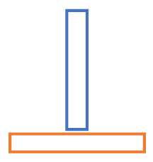
Figure 1. Flat Edges - Choose Rounded edges to extend external
borders of the component by a cylinder having the diameter of
the component thickness.
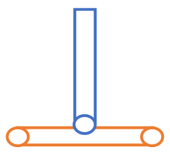
Figure 2. Rounded Edges
- Choose Flat edges to consider external
borders of the components flat.
-
Click Check.
Once the check is complete, the browser populates with detected intersections and/or penetrations.
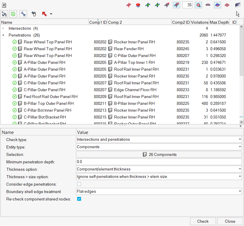
Figure 3.
-
In the Penetrations browser, click
-
Review the penetrations/intersections using the view controls in the browser.

Figure 4. -
Fix the penetrations/intersections.
To fix Do this Manually - Select groups/components to fix in the browser.
- Click
 on the collision toolbar. Additional
tools display.
on the collision toolbar. Additional
tools display.
Figure 5. - Select the elements or nodes to move.
- Move and/or translate the selected elements/nodes.
- Click
 to recheck that the
intersection/penetration no longer remains.
to recheck that the
intersection/penetration no longer remains.
Automatically - Select groups/components to fix in the browser.
- Click
 on the collision toolbar.
Tip:- If a component is intersecting with another, right-click on the component and select Find Matching Penetrating Component Pair from the context menu to find the same pair of components in the penetrations list. If the pair does not penetrate, a message will display.
- To keep a specific component from changing when performing
de-penetration fixes, right-click on that component and select
Lock Component from the context menu. A red padlock displays on the
component name in the browser to indicate that it has been locked.
The nodes in a locked component cannot be moved by the Collision
tool. To unlock, right-click a locked component and select
Unlock Component from the context menu.
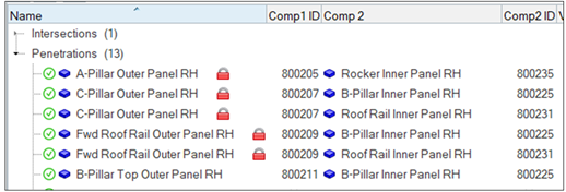
Figure 6. - Sort the columns in the browser by clicking the column headings. For example, clicking the Violations heading sorts the parent components according to their number of violations. A small triangular arrow in the column heading indicates whether the components are sorted in ascending or descending order; repeated clicks toggle between these two options.
Penetration Check Browser
Overview of the Penetration Check Browser user interface.
Collision Toolbar
| Option | Description |
|---|---|
| Invokes the collision setup widget, which can be used to setup the Penetration Check and check for intersections/penetrations. | |
| Reruns the collision check. This is recommended when you modify any attributes that control the collision check, or when a mesh modification has occurred. | |
| Automatically attempts to fix the intersections/penetrations you have
selected in the browser, based on the settings found in the
Options dialog. You can perform a fix on all of the intersections/penetrations listed in the browser, but it is highly recommended that all intersections are resolved before any automatic penetration fix is executed. |
|
| Enables you to manually fix intersections/penetrations. When selected, additional tools display in the browser that can be used to perform manual, rather than automatic, penetration fixes. | |
| Exports the result of the collision run to a .txt or .csv file. Nodes and nodes + element pairs are supported. |
|
| When multiple collisions are displayed in graphics area, click this button to identity the collision pairs in the collision browser after making a seletion in the graphics area. | |
| Displays a node List for selected penetration that reports penetration depth (thickness minus residual distance), thickness, relative penetration, (penetration divided by thickness) and residual distance for all penetrating nodes. |
View Controls
| Button | Action |
|---|---|
| Highlights all elements that caused penetrations or intersections when you select a component in the browser. | |
| Makes all elements transparent (wireframe) except for the interacting elements of the component that you selected in the browser, which display in a solid color. | |
| Displays a color gradient of the penetrating elements in the selected
component, which indicates the severity (degree) of penetration for the
interacting elements. This mode is not available for intersections because their depth cannot be determined. |
|
| Displays a color gradient of relative penetrating elements. | |
| Displays individual vectors for each penetrating element in the component
that you select in the browser. These vectors indicate the direction and depth of
penetration for both the selected component and its interacting components. This mode is not available for intersections because their depth cannot be determined. |
|
| Fits the failed elements to the display. In large models, this can be very helpful in finding and viewing small areas of minor penetration. Note that while this option is active, the view automatically fits to the penetrating elements of any component that you click in the browser. Click the option again to deactivate the fit mode. |
|
| Displays all elements, by unmasking all elements in the model, but not other masked entities such as model geometry. | |
| Masks everything in the model except for components with penetrations or intersections. Note that this option only applies to components for which you have run the current penetration check; other components may be interacting, but if you have not run a check on them they do not appear as interacting, and they will be masked. | |
| Masks everything in the model, including the interacting components, except for the specific elements that penetrate or intersect. | |
|
|
Masks everything in the model, including the interacting components, except for the specific elements and neighbors that penetrate or intersect. |
Manual Fix Tools
| Button | Action |
|---|---|
| Select Elements By Tree. When enabled, clicking the lowest-level component in the browser selects all of its failed elements. | |
| Select Elements Manually. When enabled, you can click each desired element belonging to the lowest-level component in the browser. This includes the ability to select non-failed elements or a sub-set of the failed elements. | |
| Select Nodes By Tree. When enabled, clicking the lowest-level component in the browser selects all of the penetrating nodes in its failed elements. This differs from Select Elements By Tree in that individual nodes can be moved to fix a penetration, thus changing the shape of a failed element, instead of moving entire elements. | |
| Select Nodes Manually. When enabled, you can click each desired node belonging to the lowest-level component in the browser. This includes the ability to select individual nodes of non-failed elements, or a sub-set of nodes belonging to the failed elements. | |
Determines the direction that you wish to manually move the selected nodes or
elements. Click the small triangle, in the bottom corner, to select one of the
following:
|
|
| Moves the selected nodes/elements by the negative amount specified in the numeric text box. | |
| Moves the selected nodes/elements by the positive amount specified in the numeric text box. |
Overview
The new Penetration Check tool in HyperMesh is designed to mimic the respective Finite Element solver on hand to the maximum extent possible. This way, identified initial penetrations are almost identical to those detected by the solvers themselves.
Most Finite Element solvers encounter two types of collisions: Penetrations and Intersections.
Penetrations
Penetrations themselves are broadly divided into two categories: Node to Segment and Edge to Edge penetrations. Most commercial Finite Element solvers offer interfaces that are Node to Segment only, or Edge to Edge only, or more often than not, a combination of Node to Segment and Edge to Edge.
- Node to Segment Penetrations
-
A node to segment penetration is encountered when a secondary node is spatially located within the thickness of a main segment:
Figure 7. -
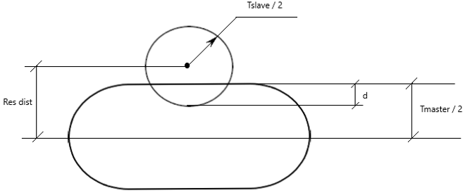
Figure 8. - In order to accurately identify nodal penetrations at segment boundaries,
like most commercial Finite Element solvers, the Penetration Check tool adds
virtual cylinders to the edges of segment boundaries as shown below:
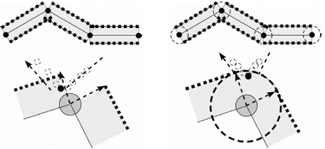
Figure 9. - Penetrations are also encountered when secondary nodes impact virtual
cylindrical edges of main segments:
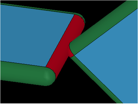
Figure 10. - For such modern interfaces in the Penetration Check tool:
- No virtual cylinders are added to the free/boundary edges of main shell elements.
- For secondary nodes of shell elements, the portion of the secondary node
spheres that lie outside the material of the shell elements are
ignored.
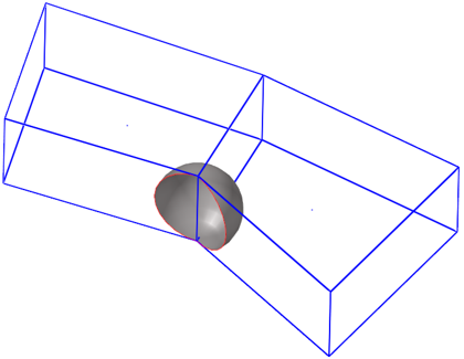
Figure 11.
Note: A secondary node sphere should not be attached to more than two free/boundary shell edges. If attached to more than two, the secondary node sphere will be retained fully.
- Edge to Edge Penetrations
-
Edge to edge penetrations are those that occur when two distinct virtual edge cylinders of segments (that do not share a common node) interfere with each other.
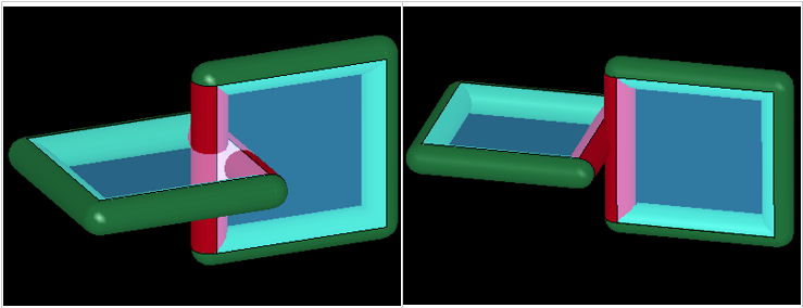
Figure 12. - Special Use Case
- Self-penetrations due to extremely thick segments. Some interfaces contain segments with large thicknesses (when compared to segment edge lengths). Depending on the type of penetration check performed, you might encounter penetrations within the same component.
- In a node to surface check, the secondary node sphere of one element penetrates
the virtual cylinder of the neighboring main segment.

Figure 13. - In an edge to edge check, two virtual cylinders on opposite edges of the
same segment penetrate each other.
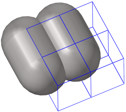
Figure 14.
Intersections
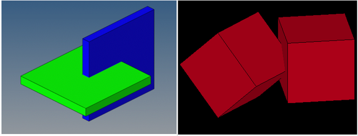
Figure 15.
Intersection checks are not a function of solver parameters and are, therefore, user-profile agnostic.
Intersections are not reported by most solvers. However, their presence will lead to severe issues during analyses, and should therefore be avoided at all costs.
Components and Groups (Contacts) Checks
The Penetration Check tool is useful for checking components for the Radioss, LS-DYNA, and PAM-CRASH user profiles.
Perform a Penetration Check
In this task you will learn how to perform a penetration check using the Penetration Check tool.
-
To display the Penetrations Browser, select from the main menu.
The Penetrations Browser displays. The Entity Editor displays beneath it. If you do not see the Entity Editor, you can display it using the Invoke Penetration Check Setup Widget button (
 ).
).
Supported Solver Contacts and Parameters
In this section you will find contact and parameter information for the LS-DYNA, PAM-CRASH, and Radioss solver cards.
LS-DYNA Solver Contacts
| Group Type | Node to Surface | Edge to Edge | N2S Treatment when thickness > edge length |
|---|---|---|---|
| SINGLE_SURFACE | Yes | No | Optional, 40% of minimum edge length |
| AUTOMATIC_GENERAL | Yes | Yes | Optional, 40% of minimum edge length |
| NODES_TO_SURFACE | Yes | No | None |
| SURFACE_TO_SURFACE | Yes | No | None |
| SINGLE_EDGE | No | Yes | N/A |
PAM-CRASH Solver Contacts
| Group Type | Node to Surface | Edge to Edge | N2S Treatment when thickness > edge length |
|---|---|---|---|
| CNTAC Type 33 | Yes | No | Ignore neighborhood penetrations |
| CNTAC Type 34 | Yes | No | Ignore neighborhood penetrations |
| CNTAC Type 36 | Yes | No | Ignore neighborhood penetrations |
| CNTAC Type 37 | Yes | Yes | Ignore neighborhood penetrations |
| CNTAC Type 43 | Yes | Yes | Ignore neighborhood penetrations |
| CNTAC Type 46 | Yes | Yes | Ignore neighborhood penetrations |
Radioss Solver Contacts
| Group Type | Node to Surface | Edge to Edge | N2S Treatment when thickness > edge length |
|---|---|---|---|
| /INTER/TYPE7 | Yes | No | Optional, ignore neighborhood penetrations |
| /INTER/TYPE11 | No | Yes | N/A |
| /INTER/TYPE19 | Yes | Yes | N/A |
| /INTER/TYPE24 | Yes | Yes | N/A |
LS-DYNA Solver Parameters
| Entity | Solver Parameters |
|---|---|
| *CONTROL_CONTACT | TH, TH_SF, SSTHK |
| *CONTROL_SHELL | CNTCO |
| *CONTACT | SST, SFST, MST, SFMT, SLDTHK, SOFT, THKOPT, SHLTHK, SHLEDG, SRNDE, MSTYP, SSTYP |
| *PART | OPTT, SFT |
| *SECTION_SHELL | T1, NLOC |
| *ELEMENT_SHELL | THIC1, THIC2, THIC3, THIC4, OFFSET |
PAM-CRASH Solver Parameters
| Entity | Solver Parameters |
|---|---|
| CNTAC / | Hcont, ITPRT |
| PART / | TCONT, H |
| SHELL / | H |
| TSHEL / | H |
Radioss Solver Parameters
| Entity | Solver Parameters |
|---|---|
| /DEFAULT/INTER/TYPE7 | IGap, IRem_Gap |
| /DEFAULT/INTER/TYPE11 | IGap |
| /DEFAULT/INTER/TYPE19 | IGap |
| /DEFAULT/INTER/TYPE24 | IPen0, Inacti |
| /INTER/TYPE7 | IGap, GapMin, GapMax, FScaleGap, IRem_Gap, %Mesh_Size |
| /INTER/TYPE11 | IGap, GapMin |
| /INTER/TYPE19 | IGap, GapMin, GapMax, FScaleGap |
| /INTER/TYPE24 | IPen0, Grnod_Ids, GapMax_S, GapMax_M, PenMax, Inacti |
| /PART | Thick |
| /PROP | Thick |
| /SHELL | Thick |
| /SH3N | Thick |
Node List for Selected Penetrations
After performing penetration checks, detailed information regarding penetrating secondary nodes can be viewed in the node list for selected penetrations.
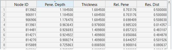
Figure 16.
- Node ID
- IDs of the penetrating secondary nodes.
- Pene. Depth
- The maximum penetration depth for each secondary node listed.
- Thickness
- The gap (or thickness) value corresponding to the maximum of all penetration depths for each secondary node listed.
- Rel. Pene
- The relative penetration value for each secondary node listed. Relative Penetration = Penetration Depth / Thickness.
- Res. Dist
- The residual distance (or physical distance) between the mid-plane of the main segment and the center of the secondary node sphere.
- The secondary node is listed only once (despite multiple penetrations of multiple entities)
- The information listed against it corresponds to the maximum of all its penetration depths
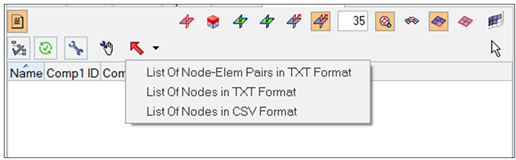
Figure 17.
Note that the plain-text report does not distinguish between Node to Surface and Edge to Edge penetrations. In both cases, the report provides pairs of secondary nodes and their impacted main elements. For solid main elements, indices of impacted faces are also included.