LS-DYNA Interface
Overview of the LS-DYNA interface.
HyperMesh provides a complete pre-processing environment for preparing LS-DYNA data decks for analysis.
HyperMesh can read existing LS-DYNA decks, create a model, display and edit LS-DYNA cards as they will look in the deck, and write a deck for analysis.
To create LS-DYNA decks in HyperMesh, you must load the LS-DYNA user profile with the appropriate template to access the full pre-processing capability.
Import and Export
- HyperMesh supports LS-DYNA solver versions through solver version 971_R12.0.
- For an LS-DYNA R11.1 and later profile, keyword attribute comments are written in the exported deck.
- HyperMesh supports LS-DYNA Long and i10 formats.
- Solver specific import options are available during import in the Solver Options tab.
- HyperMesh supports LS-DYNA Dummy models with the Primer and LSTC dummy information format. HyperMesh writes out the dummy information on Primer format.
- Most IDs in the solver deck are preserved in HyperMesh. If a keyword is not supported in a dedicated HyperMesh entity to ensure its unique ID-Pool, then HyperMesh renumbers those keywords when ID conflicts are detected. The new IDs are posted during the import process.
- The LS-DYNA interface supports a smart, reliable FE input reader that warns you when your input deck contains unsupported fields and unsupported data lines.
- HyperMesh supports parameterized IDs for Components, Materials, Properties, and Curves.
- HyperMesh supports undefined entities. These are entity IDs which are referenced in keywords (for example a Material ID in a *PART) but not defined in the deck. In this case, HyperMesh creates a default card (for example a material of type *MAT_ELASTIC is then created) in order to preserve the ID. This keyword has the Defined checkbox toggled off and is automatically not exported.
Duplicate ID’s
- Several LS-DYNA keywords are mapped to one HyperMesh entity in some instances. By default, the LS-DYNA interface doesn’t allow duplicate IDs within the same HyperMesh entity, with exception of elements. LS-DYNA allows duplicate ID’s across cards mapped to one HyperMesh entity. In HyperMesh, ID flexibility similar to LS-DYNA can be enabled by selecting and activating the allow duplicate IDs option.
- Duplicate ID's are supported for the following HyperMesh entities in the LS-DYNA user profile: elements, properties, entity sets, sensors, Load collectors and control volumes.
Mass Calculations
- Mass supplied by *PART_INTERIA card is used instead of calculating the mass based on the individual elements. Also, mass calculations include the mass supplied on the *CONSTRAINED_NODAL_RIGID_BODY_INERTIA cards.
- Shell element thickness for volume calculation is one of the following:
- Thickness on the first node for uniform thickness shells
- Average thickness at three or four nodes for non-uniform thickness shells
- The thickness values come from the *SECTION_SHELL card, unless a *ELEMENT_SHELL_THICKNESS card is defined for an element. If an *ELEMENT_SHELL_THICKNESS card is defined, its thickness values override the thickness values from the *SECTION_SHELL.
- Integrated beams have an area equal to the average of the two end areas. Resultant beams use the area entered on the *SECTION_BEAM card. The volume is calculated by multiplying the length of the beam with the *SECTION_BEAM card area. Discrete beams use the volume supplied by the *SECTION_BEAM card. In all cases, if an *ELEMENT_BEAM_THICKNESS card is defined for an element, then the element values override the *SECTION_BEAM values.
- Only element masses are considered. Other mass specifications, such as on a rigid wall card, are ignored.
Recommended Process
Editing an LS-DYNA Model to Add Cards not Supported
Use unsupported cards with the LS-DYNA model by adding them in HyperMesh. There is no need to use a text editor. Select unsupp_cards in the Control Cards panel. You can then enter the cards in the pop-up text editor. Use caution regarding formatting and card validity. Care should also be taken if any of the cards point to entities, such as cards pointing to sets and parts. These cards are stored as text and pointers are not considered. When importing an LS-DYNA mode, any cards that are encountered that are not supported are written in this section, therefore they are exported along with the remaining model.
Blanks
In the Card Editor all of the attribute fields are supported as Blanks. You must click the field and input the value.
LS-DYNA Mass Calculation
Mass calculation for LS-DYNA is accessible from the Summary panel (Post page).
The mass reported is not simply calculated by Density x Volume for each part. It follows the many LS-DYNA requirements to handle rigid body mass, non-structural mass, and lumped mass.
- Structural Mass
- Volume x density; except in case of *PART_INERTIA in which it is also the total mass.
- Lumped Mass
- Accounts for contributions from *ELEMENT_MASS, *ELEMENT_MASS_NODE_SET, and *ELEMENT_INERTIA. This does not take into account the transfer of lumped mass to rigids.
- Non structural Mass (NSM)
- Accounts for contributions from ELEMENT_MASS_PART, ELEMENT_MASS_PART_SET, and NSM in *SECTION. This does not take into account the transfer of lumped mass to rigids.
- RigidBodyMass Mass
- Mass of *CONSTRAINED_NODAL_RIGID_BODIES.
- Transferred mass
- Mass transferred from deformable nodes to rigid materials. This includes lumped mass
transferred from rigid or deformable nodes to the rigid materials.
- For rigid material, this is the mass gained from deformable (+).
- For deformable parts, this is the mass lost to rigid material (-).
- Distributed Mass
- Mass distributed from nodal rigid bodies to free nodes.
- Engineering Mass
- Mass of the part that most closely matches its real engineering meaning. The engineering mass is the most useful for possible mass adjustments. Engineering mass is the sum of structural, non-structural, and lumped mass.
- LS-DYNA Part Mass
- The mass listed in d3hsp, where you also have COG information.
Deck Export
Supported LS-DYNA files that can be exported.
- LS-DYNA v971_R12.0, v971_R11.1, v971_R10.1, v971_R9.3, v971_R8.0, v971_R7.1, v971_R6.1, input files in Keyword format.
- By default, the LS-DYNA user profile outputs v971_R12.0 .key files.
- Two templates are also provided to output the defined curves in the database:
- To output curves in Keyword format, use the curves.key template
- To output curves in Structured format, use the curves.seq template
Elemental Time Step Calculations
Time Step Calculations.
Critical Time Step for Shell (2d) Elements
 Figure 1.
 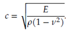 Figure 2.
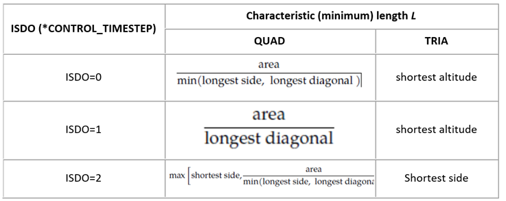
Figure 3.
Critical Time Step for Solid (3d) elements

Figure 4.

Figure 5.
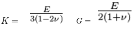
Figure 6.
Where E is Young's modulus, ρ is Material density, 𝜐 is Poisson's ratio, K is Bulk Modulus, and G is Shear Modulus..
Characteristic length:
8 node solids: 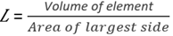
4 node tetrahedras: Le = minimum altitude
Critical Time Step for Beam (1d) Elements
Hughes-Liu beam and truss elements, the time step size is given by:
Figure 7.
Figure 8.
Where E is Young's modulus, and ρ is Material density.
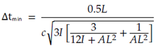
Figure 9.
Where I and A are the maximum value of the moment of inertia and area of the cross section, respectively.
Critical Time Step for Spring/Discrete Elements
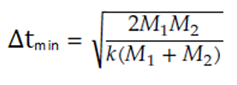
Figure 10.