Intersection
Configurations for the intersection check functionality.
GUI Default Settings
- tolerance
- Depth of the intersection to be filtered. Intersection less than this
value will not be reported in the PowerPoint.
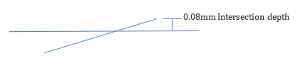
Figure 1. - slide-number
- The starting number is shown in the top right corner of the PowerPoint
file.
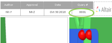
Figure 2. - report
- Initial directory for report output path.
- action
- User action type to be executed.
- Check
- Only intersection check will be executed, no reports.
- Report
- Only Reports will be generated from the previous check
- Both
- Check and Report generation will be executed in a sequence.
- mode
- Default options for Run type.
- interactive
- Check executed in the front ground Engineering Solutions session
- background
- Check executed in the background Engineering Solutions sessions. Automatic restart executed. If errors occur, the errors will be displayed in the browser as "Crash" keyword.
- logic
- Algorithm used for the checks.
- allcomp
- All parts will be imported, and check will be executed. Faster than “loop” logic, but it requires good PC hardware.
- subsystem
- Checks are executed across two subsystems. If two or more subsystems are selected from the tree or selected via assembly-level option all parts will be checked. If one sub-assembly is selected from tree or assembly the level is 0.
- Clearance_Zone (CL)
- Clearance value will be assigned on the CAD data during the intersection
check. Half of the value will be assigned on each side of the CAD data.
Increasing the value might increase the execution time.
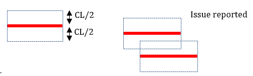
Figure 3.
Filter Settings
- revision-check
- New revisioned CAD data and its surrounding CAD data will be checked for intersection if this option is ON. All the CAD parts irrespective of revision will be checked if this option is turned OFF.
- revision-folder
- Initial directory for selecting the revision CAD data. The file name is compared against files in the selected folder. CAD files will be replaced and the revision flag is ON for that part.
- body-type
- Special treatment based on the name.
- METAL-METAL
- All the parts inside the METAL folder will be checked.
- TRIM-TRIM
- All the parts inside the TRIM folder will be checked.
- METAL-TRIM
- Parts across METAL and TRIM folder will be checked. No check will be executed inside the METAL or TRIM folders.
- Max-number-solids
- Parts will not be considered for the check if the number of solid CADs inside a part exceeds this number. This is done to avoid check on solid spot welds or harness cables.
- loopLimit
- Two parts will be compared if the value is 0. If more than 0, parts (specified # of parts) are loaded at once in one Engineering Solutions session and comparison will be executed.
- min-areapercent
- Minimum area of a part that must be considered for the check. Area of the part less than this will be ignored in the check. This is implemented to avoid small parts that do not have a proper Name or Part Number.
- min-Diagonal-BBox
- Minimum bounding box diagonal length of part that must be considered for the check. Diagonal length of the part less than this will be ignored in the check. This is implemented to avoid small parts that do not have a proper Name or Part Number.
- bbox-view
- Bounding boxes for each part are displayed in the Engineering Solutions graphics for reference after the check and report
is done. You can check if both CAD or FE is at the same place or is the
same size.
- Grey box
- Indicates # CPUs
- Green box
- Indicates bounding box of the parts.
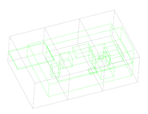
Figure 4.