The morphing capabilities of Engineering Solutions enable
you to generate new designs based on an existing mesh, in a simple and quick manner, and can be
accessed via the Morphing option in the menu bar of the CFD user
profile.
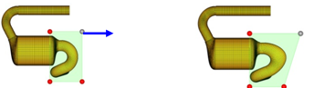
By specifying deformable regions on the mesh (MorphVolumes, green boxes in the image below)
the included nodes/cells are allowed to deform. Moving the corner nodes of the MorphVolumes
(red dots in the image below) deforms the included mesh part in a smooth manner and defines
a new design. By scaling the mesh deformation, a variety of new designs can be defined. Figure 1. Morph Volumes
Different approaches to mesh morphing that are well suited for CFD applications are
available. A wide range of constraints are provided to restrict the movement of nodes during
morphing, for example to deal with non-matching interfaces or to preserve the boundary layer
thickness. The following section gives a short description of some morphing capabilities
well suited for CFD applications.