These tools enable the creation of 1D elements from surface lines, organizing them
into components. They also offset/orient these elements based on the attached shell elements
and calculating properties of these 1D elements from 3D solid or shell FE element sections.
Beams From Lines: Create
Use this tool to create 1D elements to match the existing shell elements from lines
(surface edges). Normally surfaces are split into panels using lines and planes.
Then shell meshes are created on those split surfaces. This tool extracts 1D
elements to match the shell elements along the split lines of the surface and
separates them into predefined components based on system direction. Each system
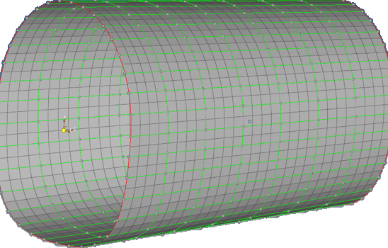
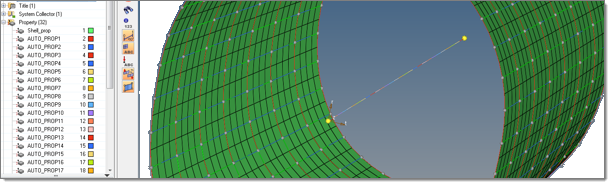
direction can have different types of 1D elements (bar, beam or ROD properties). Figure 1. A Shell Element Model with Panel Surface Edges (Green Edges) Where the
Beam Will be Created
Select all of the surface edges. This tool works on surface edges without
free floating lines. Therefore, you need to mask or delete all of the free
lines.
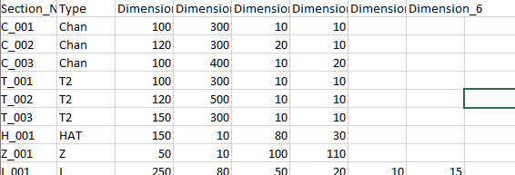
From the menu bar, click Aerospace > Beams > Beam Section from CSV to import the standard beam section from a
.csv file. In this example the CSV format and the
+Y axis of the beam will be aligned with the shell normal. Figure 2. Standard Beam Section Definitions from a
.csv File
Select Local as the System Type.
Assign beam section to each system axis. If the axis does not need a beam,
you can make the selection Unspecified.
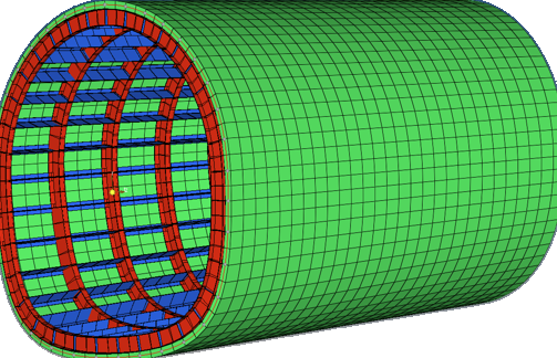
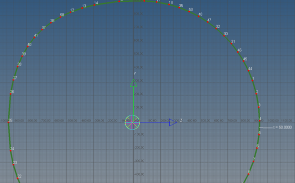
Click Create. A beam will be created with the correct
beam section properties and type (CROD, CBAR, CBEAM) along each system
axis. Figure 3. 1D Elements are Created to Match the Shell Elements and Correct
Beam Sections are Assigned
Beams From Lines: Organize
This tool is identical to the Assembly Organize by Coordinate
System tool. The purpose is to separate
all of the 1D beam elements into components based on local system directions.
Create empty components in each system direction.
Move the beams automatically to those components.
Beams From Lines: Update
Use this tool to update 1D element properties, change the orientation, or assign
offset to existing BEAM elements. The offset and orientation is based on the
attached shell element normal and shell element thickness.
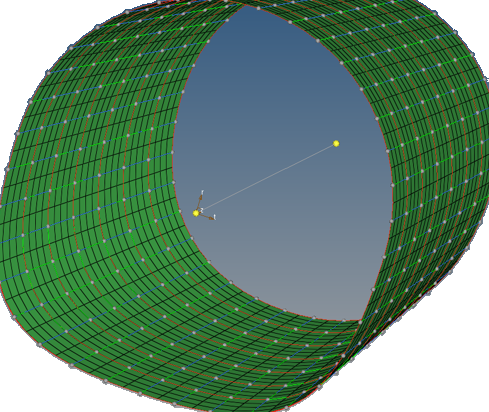
Using the beam Update tool, beam sections can be automatically calculated from 3D
solid or FE shell/beam models.
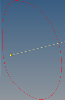
The beam properties are calculated from the FE model and are assigned to the center
beam (the white line in the middle). Figure 4. Figure 5. Figure 6. Beam Properties are Calculated and Assigned to Each Beam
Beams From Lines: Display
Use this tool to quickly display the beam properties without using the HyperBeam tool or using 3D beam display.
Click Pick.
In the graphics area select a beam.
Click Display to see the beam's property values.
Click Clear and repeat the process for the next
beam. Figure 7.