Combined Loading Tutorial
Below are the steps to perform Combined Loading operations -
To verify the combined effects
-
Select
Allline from E-Line(s) Selection list and click Summary Analysis.This will execute and run the detailed analysis for the combine loading effect. You can observe the summary page for the complete simulation.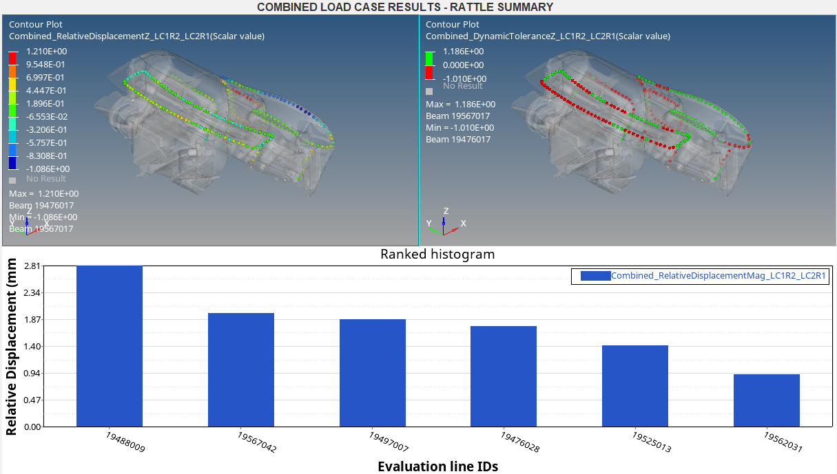 Figure 1.
 From the summary page, it can be observed that the ELine
19488009has the maximum relative displacement of value2.81 mmunder combined loading effect. You will run the further evaluation on this line. -
Now select
19488009from E-Line(s) Selection list and click Full AnalysisThis will plot the results for the selected line.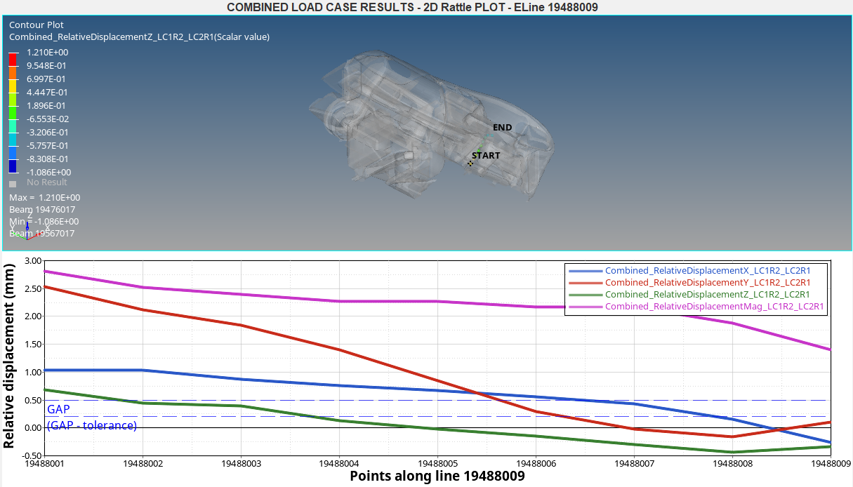 Figure 2.
To verify thermal effect on gap
With the Affects Gap box checked, you will verify the effect of thermal expansion on the gaps between the parts while applying the vibration load to the system analyzed
-
Select
19488009from E-Line(s) Selection list and click Full AnalysisThis will run the detailed analysis for the selected line and plot the results. You can verify the summary and results pages for the thermal effect on the gap.- Summary for thermal effect on gaps -
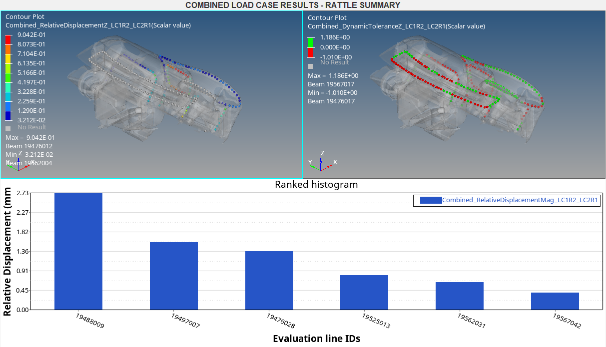 Figure 3.
 - Detailed results plot for the selected line -
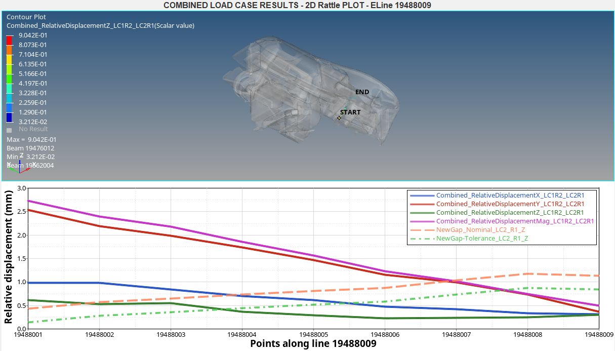 Figure 4.
 From the plots, you can observe the following -
- There is a change in the gap between the components due to
thermal expansions. Curves labeled
NewGap_Nominal_LC2_R1_ZandNewGap_Tolerance_LC2_R1_Zshow the change in gap values. - It can also be observed that the relative displacement has
reduced from
2.81 mmto2.73 mm. This analysis states that the thermal effects has reduced the relative displacement, in turn leading to reduced rattle noise.
- There is a change in the gap between the components due to
thermal expansions. Curves labeled
- Summary for thermal effect on gaps -