Altair HyperMesh 2021 Release Notes
Browsers
New Features
- Predefined filters
- Facilitates quick filtering of browser list with selected, displayed, or
current entities.
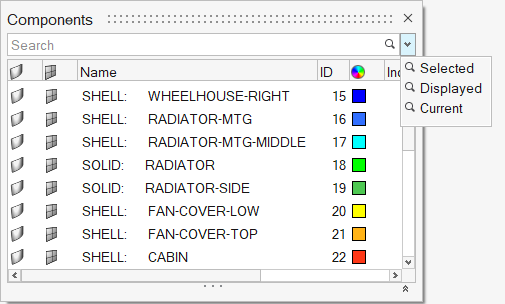
Figure 1. - Undockable Include view
- An independent, undockable Include view for managing include files can be accessed from the Include icon under the Assembly ribbon, or by double-clicking on the Include Files folder in the Model Browser.
Enhancements
- Entities under solver groupings
- Entities can be optionally displayed under solver groupings in the Model Browser by selecting the Show entities option in browser preferences.
- Entity creation by solver card
- In OptiStruct and Nastran interfaces, entities can now be created by selecting required solver card from the ‘Create’ context menu on the top-level folders in the Model Browser.
- Entity assignment
- The Assign tool, facilitating easy assignment of entities, can be invoked via a right-click context menu option. It is supported for Components, Properties, Materials, and Systems.
- Opening entity views
- Top level folders in the Model Browser can now be opened via a right-click context menu option.
- Show nested entities on filtering
- Added an option under browser preferences that facilitates listing of nested entities when a top-level entity is filtered.
- Column Filters for imaged-based columns
- Column filters are now supported for columns that have image as values.
- Suggestion list for Column Filters
- Added suggestion list for values on using column filters.
- Descriptors for Operators
- Added descriptors for operators in the auto completion suggestion list.
- Operator for ‘not containing’ search
- Added !~ (not contains) operator to search for strings not containing the specified text.
- Operator for IN and NOT IN search
- Added IN and NOT IN operators to search or exclude multiple exact values.
Resolved Issues
- Control cards was listing all cards in the Model Browser.
- Incorrect component was getting deleted while deleting empty components.
- Inactive components were displayed when referenced property was isolated.
- ‘Duplicate’ option was missing on Set entity in Sets browser.
Known Issues
- Entity Editor is not cleared when entity is removed from filtered browser list.
- Nodes are not shown in correct include when components are dragged and dropped across includes.
- Elements and nodes selected in graphics are not highlighted in browser.
- Entity views are not restored on relaunch of HyperWorks.
Composites
Enhancements
- Composite Browser
-
- Ply drag and drop logic – plies will now be placed above the target ply if dragging up, and below the target ply if dragging down.
- Material reference and ply 1 direction visualization – orientation review has been moved from the icons at the top of the browser to the ply and laminate context menus, under “Review Orientations.” The behavior is exactly like the existing Review functionality.
- Zone calculation performance improvements – for certain operations, reordering plies within a laminate and deleting plies from a laminate, performance has been improved.
- Solver Zone Property Absorption and Laminate Realization
-
- Solver attributes are now taken into account for both realize and absorb in OptiStruct, Nastran and Abaqus profiles.
- An option to delete ply based entities has been added to Laminate Realize. This should be used if the model, or properties will undergo further changes after realize. If the model is simply being exported to the solver, it can remain off.
- Composite Stress Toolbox
-
- Engineering constants analysis computes transverse shear properties for plies, laminates and zones which contain materials that include G23, G13 definition, even if corresponding Poison's ratios are missing. Supported material types: OptiStruct MAT8, and Abaqus ABAQUS_MATERIAL - Elastic: Type - LAMINA.
Known Issues
- Performance of operations within a laminate on large models
- As a workaround, a ply with no shape can be temporarily be placed in the laminate and performance will improve significantly.
Resolved Issues
- Composite Browser context menu stuck on white space options after deleting an entity.
- Ply orientations redrawn after ply orientation update.
- General undo/redo cleanup in Composite Browser.
- On spreadsheet import, shapes not assigned to plies.
- MAT8 STRN option for strain based allowables instead of stress based allowables are now taken into account by the First_Ply_Failure method of the certification browser correctly.
- Poisson’s ratio 13 and 3D stiffness and compliance matrices are now computed based on the Poisson’s ratio 31 in OptiStruct MAT9OR material card by computing ny_13 = E_1/E_3*ny_31.
- Result export (via CTRL+C and CTRL+V) now only contains selected values, including transverse shear moduli and Poisson’s ratios.
Connectors
New Features
- Connector Edit Mode
- Expanding on the workflows introduced in 2020.1.1, an existing connector can now be selected and interactively edited. The option is available for you to select a connector and interactively change the control, trim, move and adjust the density and spacing.
- Autopitch Improvements
- The autopitch tool was improved adding the ability to create a spot line so all the spots along a flange can be a single connector. You can now define the number of maximum links needed on the connector.
- Connector Line
- Connector Seam lines and Spot Lines have undergone changes to improve
how they capture significant geometrical points along the connector. See
images below. Pre-2021 displays how the connector has a test point on
either side of the corner. 2021 displays the significant point on the
corner.
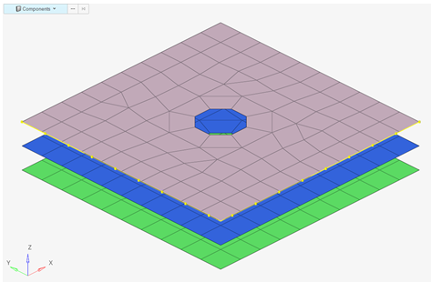
Figure 2. Pre-2021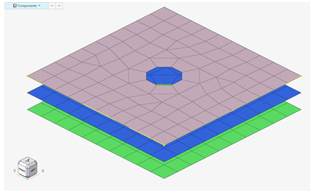
Figure 3. 2021 - FEMFAT Spot Welds
- We have introduced a new type of realization for spot welds called FEMFAT. This conforms to the specifications of naming conventions for the MAGNA FEMFAT requirements. It is available in OptiStruct, Nastran and Abaqus user profiles
Design Space
New Features
- New dedicated Design Space environment to prepare, create, and edit design spaces for topology optimization. The Create, +/-, and Connect Voxel tools have been moved from the Mesh to the Design Space ribbon.
- New local design space tool has been added. With minimal preparation, it can
create a design space contained within a user-defined volume. An example
would be structural inserts/baffles within an automotive BIW:
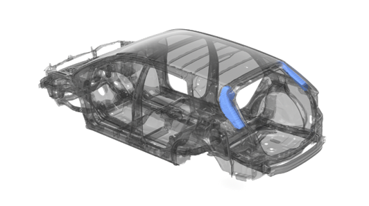
Figure 4. - New RBE3 connect tool. Connects design space to structure via RBE3s.
- Added new options to control voxel creation via the options menu:
- Intersections and voids
- Voids only
- Intersections only
- New shortcuts to tools that help with the package management preparation for
design space creation:
- Hole/Gap fill
- Shrink Wrap
- Added shortcut to the contact browser so that TIE contact can be created
manually.
TIE contact is automatically created in the local design space tool.
General
New Features
- View Cube
- A new view cube near the global triad in HyperWorks gives you direct access to standard views along with many more variations and orientations of standard, isometric, and edge views. Configure the view cube in .
-
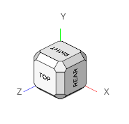
Figure 5. - Mirror
- New HyperWorks Mirror workflow added for reflecting entities across a symmetry plane.
- Scale
- New HyperWorks Scale workflow added for scaling entities with respect to origin or user defined node.
- New By Path selection options
- The following new options are available when selecting nodes, lines, or
elements By Path in HyperWorks, accessible
via Spacebar, the menu, or the
 button.
 - Current collector widgets in status bar
- New buttons in the Status Bar area show the name and ID of current
collectors in the HyperWorks session.

Figure 6. - Right-click on any button to customize the status bar buttons area. You
can show or hide any combination of available items.
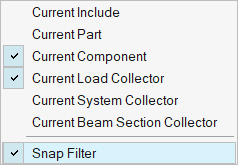
Figure 7.
Enhancements
- Scripting Toolbar
- Scripting toolbar to run TCL script and command file in HyperMesh Desktop has been restored. This tool bar was removed in the 2020.1 release.
- Undo/Redo
- Undo/Redo support is extended to many TCL modify commands.
- Marker Support
- Marker support in Entity Editor.
- Duplicate Tab Names
- Support of duplicate Tab names.
- Section Cuts
- Cross Sections are now editable inside and outside of the Section Cut tool in HyperWorks. Drag the frame to translate or the inner edge to rotate.
-
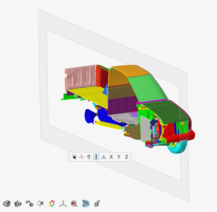
Figure 8. - Legend
- Following enhancements added to the element quality and thickness legends:
- Improved formatting of selector labels
- Single named selections now also use the consistent format “name/label
[id]”, and can now abbreviate name and id independently when exceeding
maximum display length.
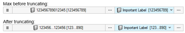
Figure 9. - Selector panels replaced
- Entity selector is now used in place of selection panels for dialogs and custom scripts. This is the same selector used in all next generation tools and the Entity Editor. It appears nearest your cursor on invoke and contains all supported advanced selection methods, right-click menu options, and quick selection methods (Alt key).
-
Figure 10. - Simplified right-click Select menu
- Removed additional sub-menus in HyperWorks
so all available selection methods and actions are now available
directly under .
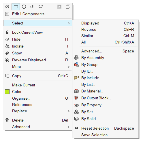
Figure 11. - Apply, Ok, Cancel buttons for advanced selection from Entity Editor
- Updated button behavior when using the advanced selection dialog from
the Entity Editor, accessible via Spacebar, the menu, or the button on any active selector.
-
- Apply: Accepts dialog selections and returns to the interactive
selector. Clicking
 or
or  on the selector is required to confirm the final
selections.
on the selector is required to confirm the final
selections. - OK: Accepts current selections and immediately confirms and closes the interactive selector.
- Cancel: Rejects current selections and immediately closes the interactive selector.
- Apply: Accepts dialog selections and returns to the interactive
selector. Clicking
- Language localization
- A new Chinese language profile has been added to HyperWorks 2021 and can be switched on via the Preferences menu. Currently, most ribbon tools have been translated. Where no translation has been done yet, English will be used. Workflow will be translated in the next release cycle.
Resolved Issues
- Crash associated with merging HyperMesh file in batch mode.
- Improvements made in reading binary STL.
- Export issue with very large coordinate values.
Geometry
New Features
- Ruled
- New HyperWorks Ruled workflow added for generating surfaces and solids by interpolating linearly or smoothly between given set of lines or surfaces respectively.
Enhancements
- Drag
- Drag lines and nodes into surfaces has been added with “Auto-trim” option. With this option, the newly created surface is trimmed at the intersection of another surface or elements.
- Lines
-
- Polylines can be modified by adding or editing existing control points, or by editing start and end slopes.
- Extend lines tool added to extend existing lines to a target node, line or surface or by using distance
- Split
- Split tool improvements include reviewing of split sections for solids
which users can select or deselect to split at desired locations only.
This helps in creating mapped solids for meshing. Following tools
support the review options:
-
- Split solids with lines and bounding lines have “Extend trimmer” option added which allows user to review the split sections.
- Split solids with surfaces with extend trimmer ON also allows the users to review the split sections.
- Split solids with plane allow users to review the split sections.
-
- Miscellaneous
- Fixed robustness issues related to lines, imprint, and boolean tools.
Meshing
General Meshing
New Features
- Midmesh inspect tool
- Midmesh inspect tool added under midmesh workflow. The tool identify/fix nodes deviating from the middle of the geometry, such as Nodes off middle, Nodes off solid edges, Nodes out of solid, Edges off solid edges, and Element centers off middle. The fix corrects the mesh to the mid by node movement or splitting elements.
- New APIs
- New API’s added for querying, updating and writing param and criteria file data individually or together.
Enhancements
Batchmesher
- Feature capture improvements
- Improved mesh flow for the geometry surfaces containing 180 folds.
- Continuous improvements in mesh flow
- Continuous improvements in mesh flow by reducing and adjusting the locations of tria elements near free edges, beads, holes and washers.
- Waviness in mesh flow
- Fixed issues with waviness in mesh flow on fillets.
- Direct midmesh
- Direct MidMesh through BatchMesher now respects the element organization specified in the parameter file.
- Split Sub-Tool
- Continuous graphical spilt line support added also explicit element selection added, user could select elements by path via advance selection and perform the split action.
- Move/optimize orphan mesh nodes
- Move/optimize orphan mesh nodes supported along and across the feature edges (PLOTEL/1D's).
- Improved smooth function
- Improved smooth function and miscellaneous bug fixes done for Edit Elements functionalities.
- Extend/trim new mapping method
- Extend/Trim new mapping method added, when there is no exact matching with the base this helps user to trim or extend their feature onto base.
- Topology based 1d selection
- Topology based 1d selection support added for Stitch/Extend edges with Alt + RMB button.
- Improved move tool handling
- Improved move tool handling and user experience, RMB and LMB clicks are mapped to easy reposition of the manipulator and move the copied feature to the destination reference point respectively.
- Quick flip
- Quick “Flip” option added in the micro-dialogue UI.
- Time step criteria
- Time step criteria added in legend for LS-DYNA and Radioss user profiles.
Solid Meshing
New Features
- Solid Map tool in HyperWorks
- Added a new “Solid Map” tool in meshing ribbon. This tool will allow
user to find mappable solids and auto detect source and target. With
this new tool, user will be able to define size on source surfaces and
add biasing on source surface edges and along edges.
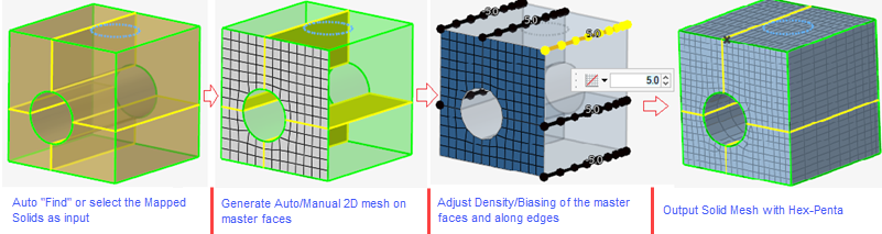
Figure 12.
Enhancements
- Enhanced fill hole algorithm
- Enhanced fill hole algorithm to follow edge shape with higher angle.
- Enhanced tetramesh remesh algorithm
- Enhanced tetramesh remesh algorithm to remesh surfaces as well.
- Auto split highly warped quads
- Added capability to auto split highly warped quads to trias. Mostly used for airbag meshing.
- Enhanced sliver fix capability
- Enhanced sliver fix capability to remove slivers on non-manifold edges.
Resolved Issues
- Segmentation error upon surface meshing with 2nd order quad mesh and then batch meshing
- Segmentation error on running adaptive tria remesh with 1d and quad inputs
- Remeshing elements crashed session with segmentation error
- Make “Quad Only” option work for solidmap meshing
- Twisted hexa elements are getting created for pipes
Model Build
General
- Support for linking multiple parts as instances
- In HyperWorks Desktop 2021, a new context
menu provides access to making multiple parts as instances of each
other.
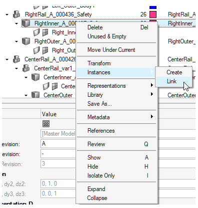
Figure 13. - Support for Matching based on Name/Metadata
- In HyperWorks Desktop 2021, a new matching
method based on Parts Name/Metadata is supported.
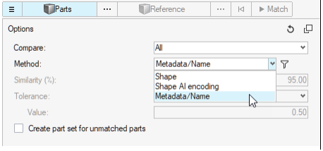
Figure 14. - Subsystems support multiple includes
- In previous versions, subsystems could only contain a single include.
This has been enhanced so that a subsystem can own multiple includes,
including a nested hierarchy, without forcing you to merge include
contents into a single include.
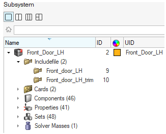
Figure 15.
Morphing
New Features
- Morph ribbon
- The mesh morphing tools have been moved from the Mesh ribbon page to a new Morph ribbon page.
- Proximity morphing
-

- The new Proximity Morph tool allows to morph mesh directly using a
simple distance or perturbation value around selected nodes, faces, or
edges. Move the mesh using the graphical manipulator, or by optionally
mapping to Target entities. Usage of this tool is analogous to the Free
Morph tool, but without the need to define anchors or morph areas,
making it a simpler and faster approach for applicable use cases. This
approach is also great for morphing surfaces of 3d meshes where only a
few element layers around the moving nodes need to be morphed.
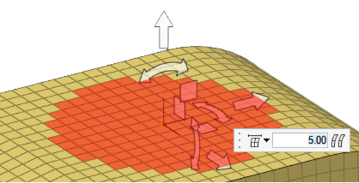
Figure 16. - Volume morphing
-

-
-

Enclose: Use the Enclose tool to create morph volumes with rectangular or circular shapes. Enclosed mesh and connectors are automatically registered to the enclosing volumes by default.
-

Move: Use the Move tool to morph or adjust morph volumes by moving vertices or handles, edges, and faces using graphical manipulators.
-

Split/Combine: Use the Split/Combine tool to split morph volumes using single or multiple locations along an edge, combine adjacent morph volumes along shared faces, join pairs of separate morph volumes, or equivalence any number of morph volume faces using a search distance.
-

Register: Use the Register tool to review and edit the contents of morph volumes. Only registered contents will morph when morphing morph volumes. Entities that can be registered to morph volumes are nodes and connectors.
-
Enhancements
- Distance-based methods moved from Free to Proximity morphing
- The following distance-based options have been removed from the Free Morph tool options menu, since they are now available in better form as part of the new Proximity morphing tool:
- Optional automatic unfolding
- A new menu located in morph options > domain solvers > large domain morphing, allows controlling the automatic mesh unfolding that may takes place after certain large morphs. The new default behavior is set to ask the user before unfolding, and can be also set to always or never unfold. The unfolding process is time consuming and may not be required after every morph, especially when still iterating on the mesh shape or if the mesh will be rebuilt after morphing.
Model Verification
Enhancements
- Support of SolidWorks data is added in Comparison and Verification function.
- Cumulative match% calculation logic is improved for CAD vs FE comparison. Cumulative match% =Total target matched area / Total source matched area.
- Fe-attach function supports component name while finding attached parts in addition to shared node logic.
- Method of calculating Thickness from solid CAD is populated on the Browser and Excel report.
- Report generation time can be reduced by editing facet size under general/discretization, 1-6 level exist, Level 1 reduces time.
- Skip-thumbnailassemblyimage parameter is added to skip assembly images in
comparison thumbnail PPT report to improve performance, default=OFF.
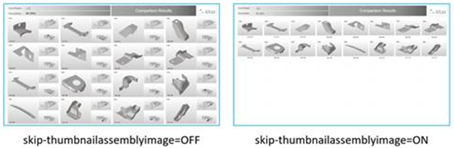
Figure 17.
- Batch mode is added for Quick Comparison and Spot Comparison function.
- HM file containing Geometric data is supported in Mixed Import option.
- Performance improved for Connection check / Free Hole, Hole Mismatch functions.
- Intersected part’s coordinates and depth values are exported in csv file by
default. File
name=ProjectName-Model_Intersection_Depth.csv under
report path.
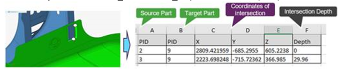
Figure 18.
General
- Reset button is added on configuration file to restore original setting.
- Auto migration of configuration file is done if old configuration is used preserving user parameters.
- Comparison and Import log messages are improved for debugging the function.
- Tool tips are added for all parameters.
- Existing Part Sets will be deleted on each execution of Part / Match function.
- Part Set name considers names from Part Name and Part Number, in addition
filtered data and unprocessed data are shown in sets.
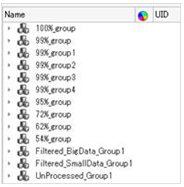
Figure 19.
Resolved Issues
- Spot Comparison, Fixed an issue on executing checks on MAT 100(Hexa) weld type.
- Spot Comparison, Fixed an issue on considers point vs. point data comparison.
- Comparison/Verification, Fixed an issue on Batch mode incorrect progress% message under progress.log.
- Comparison, Fixed an issue in Auto comparison showing false unmatched entities.
Safety Tools
New Features
- Barrier Position Tool
- This new tool, available in the Safety ribbon in the LS-DYNA and Radioss
solver interfaces, enables an automatic positioning of the crash barrier
around the vehicle as per the selected safety regulation. The tool
provides following functionalities:
- Support of all safety regulations: C-NCAP, Euro-NCAP, FMVSS, IIHS, J-NCAP and UN-R
- Support of all load cases: Front, Side and Rear
- Following positioning methods are implemented: Overlapping method, Side with IRD method, Side with R-Point method, Pole
- User-defined gap between barrier and vehicle
- Automatic creation of transformations and positions entities
- Automatic switch of the barrier include file to *INCLUDE_TRANSFORM or /SUBMODEL respectively for LS-DYNA and Radioss solvers
-
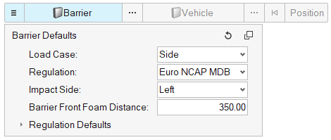
Figure 20. -
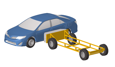
Figure 21. - Dummy Positioner: Automatic contact detection
- This new functionality enables the automatic contact detection between dummy limbs and surrounding structural components. When the contact is detected, the motion of the limb is automatically stopped and thus, avoiding intersections.
- Mechanism Tool: Automatic morphing
- This new functionality enables the automatic morphing of components using the slider joint. All morphing entities are automatically created, and the morphing happens in real time when the joint is manipulated.
-
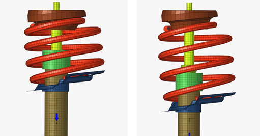
Figure 22. - Pedestrian Impact Solution
- The pre-processing the pedestrian impact regulations have been enhanced
with the following features:
- Hard parts distance contouring and offset zones creation
- Impact points refinements
-
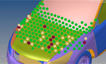
Figure 23.
Enhancements
- Graphical selection of mechanisms and dummies
- Dummies and mechanisms can be selected directly on the graphic using the Mechanism selector.
-
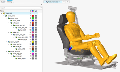 Figure 24.
Resolved Issues
- Radioss XREF are now created on import of the h3d file in the pre-simulation tools.
- LS-DYNA seatbelt extraction was not working if the break angle between the 1D belt segments was too big. This limitation is removed and a break angle control in the seatbelt extraction tool is added.
Solver Conversion
Enhancements
- LS-DYNA to Radioss Conversion
-
- *MAT_COHESIVE_MIXED_MODE_ELASTOPLASTIC_RATE/ MAT_240 converted to /MAT/LAW83, /FAIL/SNCONNECT and property /PROP/CONNECT
- *MAT_COMPOSITE_FAILURE_SHELL_MODEL / MAT_059 converted to /MAT/LAW25 (CRASURV) and the property /PROP/SH_SANDW
- *MAT_POWER_LAW_PLASTICITY_OPTION / MAT_018 converted to /MAT/PLAS_TAB(LAW36)
- *MAT_OGDEN_RUBBER / LAW_077_O converted to /MAT/LAW42 (Ogden)
- Abaqus to OptiStruct
-
- *connector section SLOT, ALIGN to OptiStruct JOINTG TRANSLAT
- *connector section JOIN to OptiStruct JOINTG RPIN
- *connector section JOIN ALIGN to OptiStruct JOINTG RBEAM
- *HYPERELASTIC MATERIAL converted to MATHE (uniaxial,biaxial,shear and volumetric)
- *CONTACT PAIR, Finite converted to CONTACT, CONSLI
- *DSLOAD converted to PLOADSF
- *SPECIFIC HEAT converted to MATT4
- *EXPANSION,ZERO is converted to MAT1,TREF
- Abaqus to Radioss
-
- /R3D4 converted to /PROP/SHELL with /RBODY
- *BEAM GENERAL SECTION converted to P3_BEAM
- *OUTPUT, FIELD,RF converted to /ANIM/VECT/FREAC
- *HYPERELASTIC MATERIAL converted to /MAT/LAW92
- *ORIENTATION converted to /SKEW/FIX
- LS-DYNA to OptiStruct
- *CONSTRAINED NODAL RIGID BODY is converted to RBODY/RBADD
- OptiStruct to Abaqus
- Nodal offsets converted from OptiStruct to Abaqus
Stress Tools
New Features
- New Certification ribbon and workflow
- A new Certification ribbon is available for OptiStruct/Nastran user profiles with end-to end workflow.
- New Config: Generic
- Along with existing configs like Rivets, Beams, and Panels (Composite or
Metallic), which come with pattern detection in model, this release
exposes Generic config. Using Generic config for Designpointset, you can
create a designpoint entity as a collection of any type or elements
(1D-2D-3D) and run Generic methods. Aside from elements, you can also
refer to Freebody sections.
Figure 25. - Run methods on elements
- In 2020.1, it was only possible to assign and run a method on a
Designpointset entity. In this new release, you can also directly run a
method entity on elements. Method is evaluated only on selected elements
for selected loadcase.
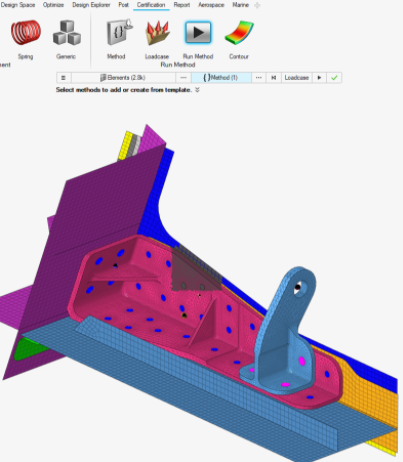
Figure 26.
Enhancements
- Structural properties
- The structural property widget is deprecated and migrated to the Model
Browser, which enables all features like “add column”.A dedicated browser tab is added to create and assign structural properties.
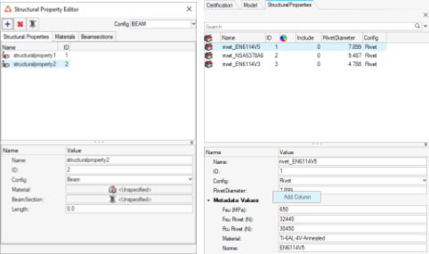
Figure 27. - Contour and Marker plots
- Along with contouring results on elements, it is now possible to add
marker plots with shapes, decoupled from contour. You can hence marker
plot any available input value or critical loadcase. In the event where
multi method ran on the same location, a consolidated table enables you
to plot the name of the critical method too.
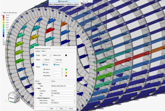
Figure 28. - Chain methods
- You can register a method taking its input arguments from the result of a previous method. They are chained methods. This was introduced in 2020.1, but the built-in rivet method JointLoad was not available as a source.
CAD and Solver Interfaces
Abaqus Interface
New Features
- Abaqus parts and instances modeling
-
- Importing a geometry and realizing it as Abaqus parts and instance format model.
- Ability to set-up part definitions like properties, and synchronize with other instances of the same part.
- Create parts and instances models in HyperWorks from scratch.
- Ability to set-up all assembly details like connections and contacts, using tools available in HyperWorks.
- Complete runnable parts and instance format input file set-up and export.
- Special elements tool for cohesive element modeling
- Cohesive elements used in debonding and delamination studies can be modeled with special elements tool available under 3D mesh.
Enhancements
- Auto Contact update
- Feature angle based individual contact surface detection is now set as default contact detection.
- Updated keywords
-
- *RIGID BODY – The reference node is updated with an option to reference a node set.
- *COUPLING – A node set can be used for the reference node when type is element based surface.
- *CONTACT FORMULATION – Support for SMALL SLIDING with SLIDING FORMULATION in general contact.
- Additional enhancements
-
- Support of *AMPLITUDE curve inside *STEP definition.
- MAX1D – Axisymmetric membrane element is supported in Standard 2D profile.
- Up to 8 nodes of an element is written in the same line upon export of input file.
- Export option for *SURFACE to be exported in list format for elements.
Resolved Issues
- PARAMETER dependency on other PARAMETERS and reconciling issue is fixed.
- Element configuration was changing when profile is changed from standard to explicit and it is now resolved.
- Beam section CENTROID, SHEAR CENTER data that are improperly imported is now fixed.
- An include file containing data lines under *FILM was not exporting, and the issue is resolved in this version.
- A *COUPLING node with surface type as node will be lost and this issue is fixed.
ADVC Interface
New Cards
- Temperature Analysis
-
- $Element Bar
- $BarSectionDirector
- $BarGeometry
- $ShearCorrectionFactor
- $LinearConstraint
- $Element 3DModifiedQuadraticTetrahedron
- $BarSectionDirector
- $InitialTemperature
- $HeatFlux
- $TransientHeatFlux
- $HeatConvection
- $SurfaceIDHeatConvection
- $TransientHeatConvection
- $TransientSurfaceIDHeatConvection
- $ForcedTemperature
- $TransientForcedTemperature
- $FilmCoefficient
- $TimeStep
- $OutputParameter Labels
- Temperature
-
- HeatFlux
- ContactNormalVector
- Stress Analysis
-
- $Element Bar
- $BarSectionDirector
- $BarGeometry
- $ShearCorrectionFactor
- $BarOffset
- $InterpolationConstraintElement
- $RigidBar
- $LinearConstraint
- $Element 3DModifiedQuadraticTetrahedron
- $InitialTemperature
- $Temperature
- $ForcedDisplacement
- $Load
- $ForcedVelocity
- $Pressure
- $SurfaceIDPressure
- $TimeStep
- $LocalCoordinateSystem
Enhancements
- Comparison and Verification browsers are added.
- Loads, BCS, Velocities, Temperature, Convection and Flux Ribbs.
- HyperBeam support for creating standard sections.
CAD Interface
New Features
- OCX
- A new Open Class eXchange (OCX) reader is now available. OCX is an open industry standard for the exchange of design information between designer/yards and classification societies. OCX v2.85 .xml schema is supported for geometry, model hierarchy, beam sections, and metadata.
Enhancements
- Updated Version Support
-
- JT 10.5
- NX 1926 (native reader)
- NX 1934 (third party reader)
- Inventor 2021
- Inspire 2021 (import and export)
- Parasolid v32.0.186
- CATIA Parameter Update
- Added support for reading and updating Catia V5 parameters in Hyperworks. This feature requires CATIA installation and CATIA license. Only parameters corresponding to a double value or a double expression are supported.
- Map multiple metadata values
- Ability to map multiple metadata values to HyperMesh PDM attribute.
Resolved Issues
- Miscellaneous import and missing cad issues with CATIA and step files.
- Fixed import hierarchy as parts for FORAN reader.
- Fixed incorrect publications data.
- Fixed transformation issues for 3DXML files.
- Miscellaneous robustness and performance improvements.
EXODUS Interface
New Features
- Marine tools
- Marine tools vertical is exposed to the EXODUS user profile with the following beam modeling tools:
- CAD property
- Beam sections
- Stiffener modeling
- Beam-shell meshing
LS-DYNA Interface
New Features
- Support of LS-DYNA solver version R12.0
- The latest LS-DYNA solver version R12.0 is now supported, along with major keywords updates and new keywords in the following groups *AIRBAG, *CONTACT, *CONTROL, *DEFINE_CPM, *DEFINE_FRICTION, *INTERFACE_COMPONENT, *MAT, *SECTION.
- Elemental time step quality criteria
- The shell elemental time step is now available as meshing quality
criteria, which adapts the quality of the mesh with respect to the
solver elemental time step value.
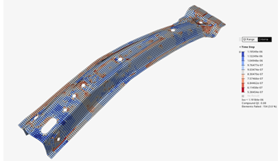
Figure 29.
Resolved Issues
- Issue 1: Multiple instances of include files into a single *INCLUDE keyword can now be imported.
- Issue 2: Corrections made to enable reading all keywords in I10 or mixed format of decks when the keyword is respectively written with a “%”, “+” or “-” at the end.
OptiStruct Interface
New Features
- Include File Drive Mapping
- On import of solver decks that contain includes, HyperWorks now allows mapping from one folder path to another to import include files where the include path written in the solver deck doesn’t match the location of the files, which includes different paths due to different operating systems. Found in Preferences > Drive Mapping or in the Solver Deck import options, you can define the source path where the files reside and the target path as written in the solver deck and use this to successfully import files without the need to edit the include paths in a text editor.
- Auto Contact Enhancements
-
- Ease of component selection from graphics to detect contact automatically with specified tolerance.
- Accept or Reject detected contact through contact traverse.
- Review, modify contact pairs using advance selection.
- Contact browser for advanced query the contact pairs created using auto contact.
- String-Based Input
-
- String-based labels offer easier identification of entries in the input file.
- Labels can be used to identify entries via their corresponding ID field.
- New solver option in export browser “Export as named entity” with free format export.
- Labels export supported for Properties and Materials entity and their corresponding references.
- Solver Browser Enhancements
-
- You can create solver cards from the solver browser.
- Cascading menu organized solver entity list.
- Ease of creation with reduced panel dependencies.
- Model Check Enhancements
-
- Check for AXIAL JOINTG elements with coincident grids.
- Check for missing CID2 for relevant JOINTG element types.
- Info to list non-zero length JOINTG elements.
- JOINTG Element Enhancements
-
- New combination joint types: RPINROTA and CARTORIE.
- DAMPING input for JOINTG property PJOINTG.
- Check elems, Free 1-d’s enhanced to identify free JOINTG elements.
- Thermal Analysis Enhancements
-
- One Step Transient Thermal Stress Analysis for nonlinear static subcase.
- New bulk card TEMPT.
- ASSIGN card updates.
Enhancements
- Updated Keywords
-
- Added CONTF output request for linear static analysis.
- Axial displacement as input for GAP elements in DRESP1 cards.
- PLOADSF updated to assign element set.
- DOPTPRM card updated with OPTIMOMP option.
- SET entity updated with subtype as property for formula-based sets.
- CFAILURE, CSTRESS and CSTRAIN output cards are updated with CORNER input in location option.
- TLOAD1/TLOAD2 enhancements to reference Temp/TempD load as excitation load with excite type as TEMP.
- KNLINE in PBUSHT accept TABELG as input.
- SECTION card name field updated to define up to 80 characters in free format export.
- PCONT card updated to input ‘LONG’ as input in FRICSEL field.
- General Enhancements
-
- Solver option in export browser to export DMIG card in long format to retain the precision.
- Tool tip description update for missing solver cards.
- Solver option in export browser to export “Include file path relative to include statement.”
Resolved Issues
- Performance improvements while import solver input file.
- OSSMOOTH for smoothing ply shape was not consistent.
- Mishandling of ASSIGN cards on import.
- OUTPUT card export trailing comma which results in solver termination.
- Unable to reference SET in RSSTRESS response type in DRESP1 card.
- ASSIGN card truncated.
- PRETENS load displays inconsistent graphics.
- Performance improvement while reviewing subcase info in entity editor.
- STRESS I/O card export issue.
- PLOAD card unsupported without CQUAD4 element.
PAM-CRASH Interface
New Features
- New PAM-CRASH 2G Solver Interface
- Added new PAM-CRASH 2G 2020 solver interface along with related major keyword updates.
- New Keywords
- New keyword Material Type 307 - COS3D (Link Material).
- Parameter Editor New GUI
- Introduced new Python interpreter GUI. Right-click edit on Expression value in entity editor to launch the new parameter editor. This new GUI allows you to create, edit, and evaluate multiple lines of python commands parameter expressions.
- ID Parameterization
- PYVAR and PYFUNC have been extended to the parameterization of ID references in other keywords. PAM-CRASH keywords SENSOR, FUNCT, FRAME, RUPMO, CDATA, CHEM, CNTPTY, DMPEW, FRICT, LAYER, NLAVE, OPTLIS have been added whose ID references in other keywords make it possible to parametrize.
Enhancements
- Updated Keywords
- BAGIN (FPM Vent Model, FPM_GASDYN, FPM Controls), CKCTRL, CNTAC (Contact NTYPE 36, 37, 43, 46, 54, 154), DELEM, ECTRL, ICTRL, LCTRL, MATER (Material Type 1, 101, 103, 151, 201), OCTRL, PART (ATYPE = BEAM), PRCTRL, RUNEND, SENSOR (ITYP = 7), TIED, TITLE, TRSFM (IDTRSFM).
- Parameters
- The following improvements are added to the python parameter
keywords:
- TITLE option added which avoids conflict with parameter name when assigned.
- Long parameter name support and no restriction of 8 character length.
- New checkbox 'Remove '+' suffix from free format fields Parameterization' in Export GUI.
- Maintain Child parameter variables references to avoid unused entities, retained after Model Checker correction.
- Reader enhancements enable robustness of parameters.
Radioss Interface
New Features
- Support of Radioss solver version 2021
- The new Radioss solver version 2021 is supported along with major keywords updates.
- Elemental time step quality criteria
- The shell elemental time step is now available as meshing quality
criteria, which adapts the quality of the mesh with respect to the
solver elemental time step value.
Figure 30. - New encryption
- The new encryption using the keyword /ENCRYPT is now fully supported and
encrypts Materials, Properties, Curves, and Failure keywords. The
encryption process can now be started from the contact menu of the
entities in their dedicated browser views. An additional column is added
to inform you about the keywords that are encrypted.
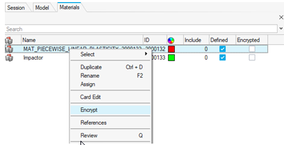
Figure 31.
Resolved Issues
- Issue 1: /BEGIN card is now editable in the Model Browser.
- Issue 2: Some keywords were incorrectly grouped as “ungrouped” into the Model Browser.